Connecting to the Host Computer and Options 71
TM-L90/TM-L90 Peeler Model Technical Reference Guide
Note:
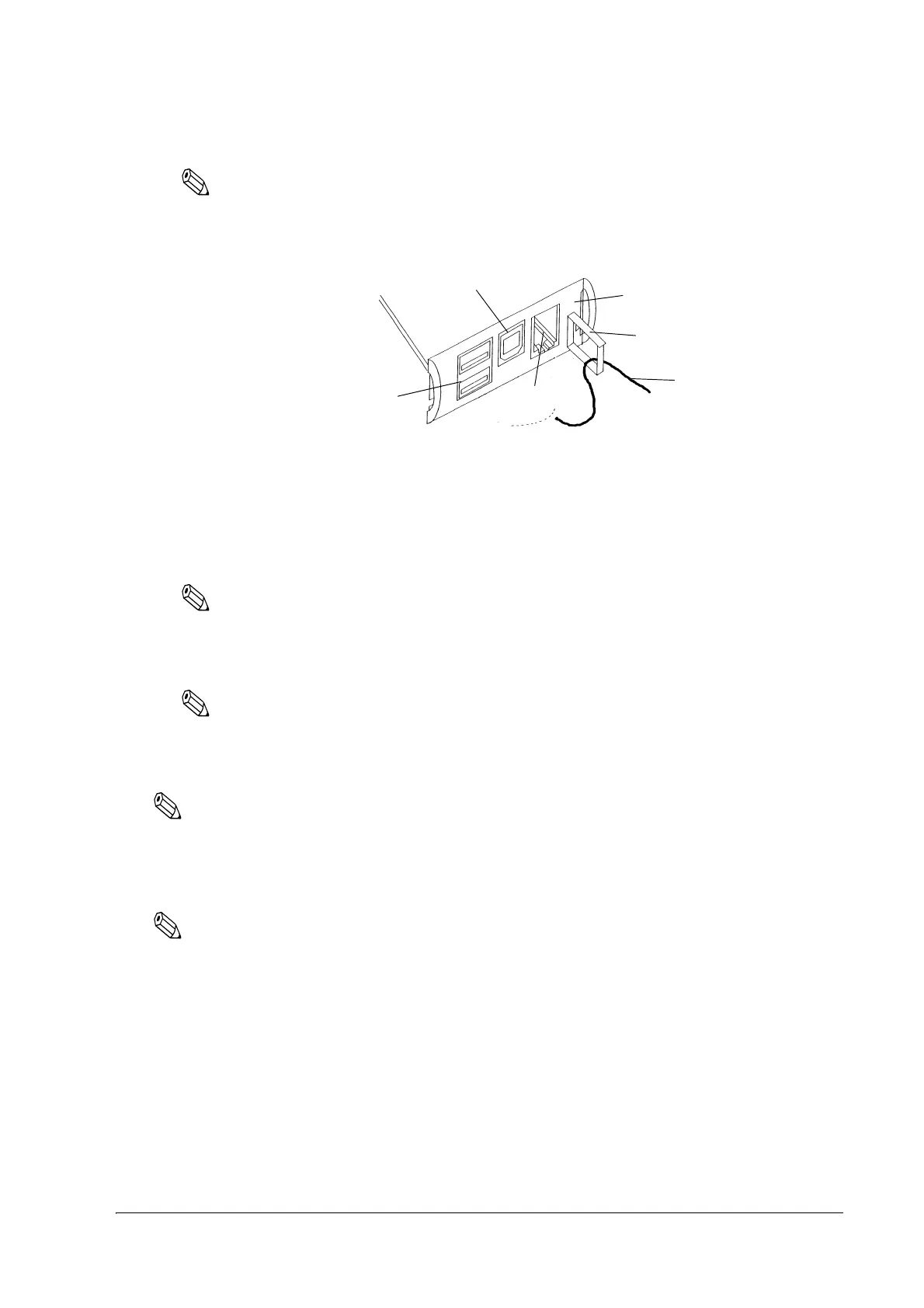
Hooking the USB cable through the locking wire saddle as shown in figure below will prevent the
cable from coming unplugged.
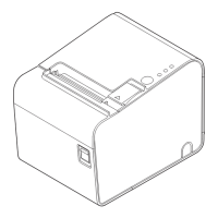
Attaching Locking Wire Saddle
3. Connect the USB cable from the host computer to the USB upstream connector.
4. For models that have the UB-U** installed, a maximum of two USB devices can be connected
to the USB downstream connector.
Note:
The hub installed in the USB model's control panel is a bus power-supply hub. Therefore, it is
important to note that bus power supply hubs (including other USB models) and bus power supply
functions with 100 mA or more consumption current cannot be connected directly to the printer.
Note:
To use USB model TM printer, you need to install the USB device driver on host computer after
connecting TM printer to the host computer. For information on how to obtain the required device
drivers and their installation procedures, contact Epson or your dealer.
Note:
The connector panel varies depending on the models.
If you connect a customer display (DM-D), set the DIP switch settings as follows. For details, see
the User’s Manual packed with your customer display.
Note:
TM-L90 other than 4** models or TM-L90 Peeler other than 39* models have the DIP switches. TM-L90
4** models or TM-L90 Peeler 39* models do not have the DIP switches; however, various functions can be
set with memory switches. For detailed information about the memory switches, see "Memory Switch
Settings" on page 44.
USB downstream connector
(Not all models)
Control panel (USB model)

 Loading...