TORCH DATA 100i-400i 128 Manual 0560956430
Aluminum
Flow Rates (SLPM / SCFH)
30A
Air
Preow
19 / 40
Air Plasma / Air Shield
Culow
40 / 85
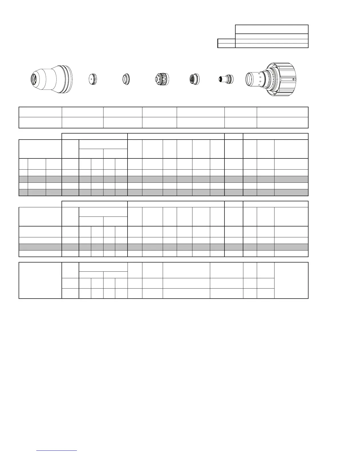
Electrode
Shield Cap
Tip
Shield Gas
Distributor
Plasma Gas
Distributor
Cartridge
Shield Cup
This Art Is For Reference ONLY
Art # A-07958_AB
Shield Cup Shield Cap
Shield Gas
Distributor
Tip Plasma Gas Distributor Electrode Cartridge
0559211201 0559210141 0559210080 0559210121 0559210064 0559210101 0559211200
Manual Gas Control Advanced Torch Height Control (THC) Basic THC CNC Control
Material
Thickness
Pre Flow
Pressure
(Air)
Cut Flow Rates / Pressures
Arc
Voltage
Cut Height
THC
Pierce
Delay
Pierce
Ignion
Height
Elevaon
Height
Control
Delay
Pierce
Height
without
Elevaon
Travel
Speed
CNC
Moon
Delay
Max Kerf Width
@ Rec. Speed
Plasma (Air) Shield (Air)
ga (in) inch (psi) Ball (psi) Ball (psi) (Volts) (in) ±0.005 (sec) (in) (in) (sec) (in) (ipm) (sec) (in)
- - 0.025 60 60 120 15 120 86 0.020 0.0 0.040 0.030 0.7 0.040 500 0.0 0.029
- - 0.037 60 60 120 15 120 86 0.020 0.1 0.060 0.040 0.6 0.060 240 0.1 0.046
- - 0.052 60 60 120 15 120 84 0.020 0.2 0.080 0.040 0.5 0.100 230 0.2 0.034
- - 0.064 60 60 120 15 120 80 0.020 0.2 0.080 0.040 0.5 0.100 220 0.2 0.036
Manual Gas Control Advanced Torch Height Control (THC) Basic THC CNC Control
Material
Thickness
Pre Flow
Pressure
(Air)
Cut Flow Rates / Pressures
Arc
Voltage
Cut Height
THC
Pierce
Delay
Pierce
Ignion
Height
Elevaon
Height
Control
Delay
Pierce
Height
without
Elevaon
Travel
Speed
CNC
Moon
Delay
Max Kerf Width
@ Rec. Speed
Plasma (Air) Shield (Air)
(mm) (Bar) Ball (Bar) Ball (Bar) (Volts) (mm) ±0.1 (sec) (mm) (mm) (sec) (mm)
(mm/
min)
(sec) (mm)
1 4.1 60 8.3 15 8.3 86 0.5 0.1 1.6 1.0 0.6 1.7 6060 0.1 1.1
1.5 4.1 60 8.3 15 8.3 82 0.5 0.2 2.0 1.0 0.5 2.5 5690 0.2 0.9
2 4.1 60 8.3 15 8.3 75 0.5 0.2 2.0 1.0 0.5 2.5 5280 0.2 1.0
Marking
Pre Flow
Pressure
(N₂)
Marking Flow Rates /
Pressures
Arc
Voltage
Marking
Height
Pierce Ignion Height
THC and CNC
Delay
Control
Delay
Travel
Speed
Marking quality
degrades as
thickness
decreases.
16A Arc Current
Plasma (N₂) Shield (N₂)
Burn-through may
happen for thicknesses
< 1/16” (0.063”) /
1.6 mm.
(psi) /
(Bar)
Ball
(psi) /
(Bar)
Ball
(psi) /
(Bar)
(Volts)
(in) ±0.005 /
(mm) ±0.1
(in) ±0.005 / (mm) ±0.1 (sec) (sec)
(ipm) /
(mm/ min)
20 / 1.4 20
40 /
2.8
70
80 /
5.5
93 0.100 / 2.5 0.100 / 2.5 0 0.7
300 /
7620
BOLD TYPE indicates maximum piercing parameters.