Manual 0560956430 163 TORCH DATA 100i-400i
Aluminum
Flow Rates (SLPM / SCFH)
200A
H35 N₂
Preow
- / - 62 / 132
H35 Plasma / N₂ Shield
Culow
33 / 71 44 / 94
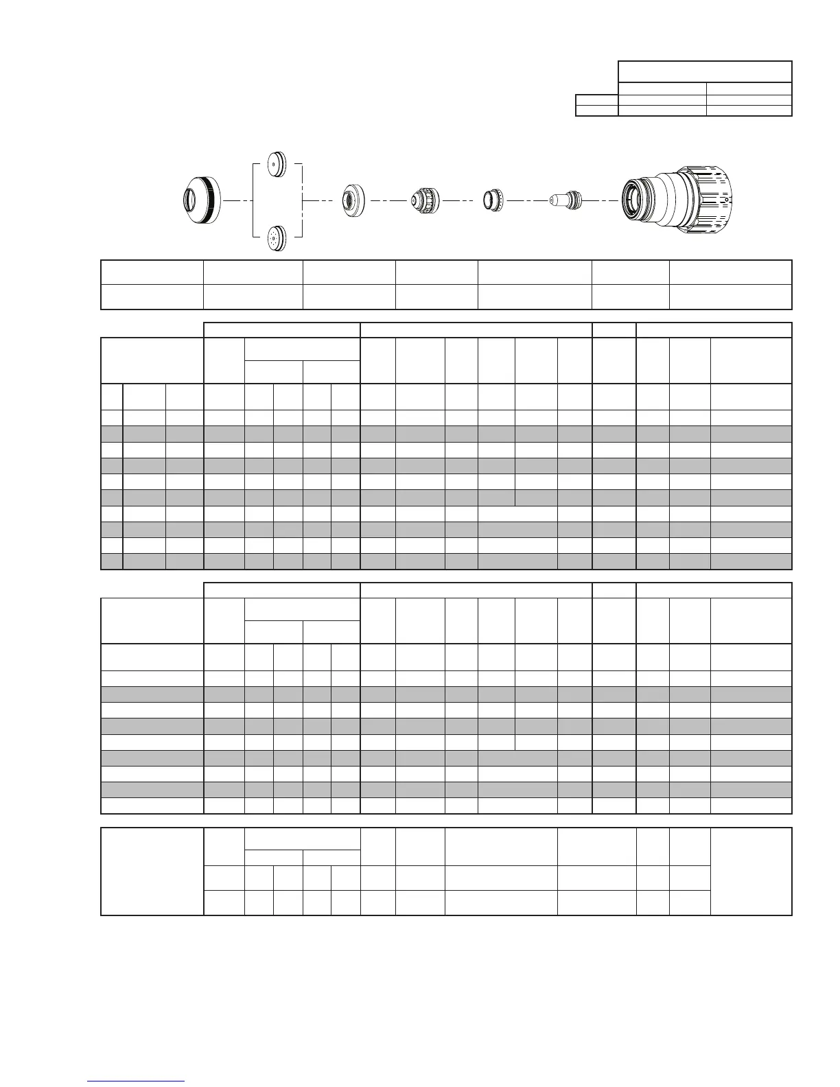
Electrode
Shield Retainer
Tip
Art # A-08567_AB
Plasma Gas
Distributor
Cartridge Assembly
This Art Is For Reference ONLY
Shield Cap
Shield Gas
Distributor
Shield Retainer Shield Cap
Shield Gas
Distributor
Tip Plasma Gas Distributor Electrode Cartridge
0559211211
< 1” / 0559210149
≥ 1” / 0559210148
0559210082 0559210128 0559210062 0559210110 0559211300
Manual Gas Control Advanced Torch Height Control (THC) Basic THC CNC Control
Material
Thickness
Pre Flow
Pressure
(N₂)
Cut Flow Rates / Pressures
Arc
Voltage
Cut Height
THC
Pierce
Delay
Pierce
Ignion
Height
Elevaon
Height
Control
Delay
Pierce
Height
without
Elevaon
Travel
Speed
CNC
Moon
Delay
Max Kerf Width
@ Rec. Speed
Plasma (H35) Shield (N₂)
ga (in) inch (psi) Ball (psi) Ball (psi) (Volts) (in) ±0.005 (sec) (in) (in) (sec) (in) (ipm) (sec) (in)
- 3/8 0.375 20 100 100 NA 110 165 0.300 0.2 0.300 0.250 0.2 0.400 180 0.2 0.113
- 1/2 0.500 20 100 100 NA 110 168 0.300 0.2 0.250 0.200 0.4 0.350 150 0.2 0.119
- 5/8 0.625 20 100 100 NA 110 170 0.300 0.5 0.250 0.200 0.3 0.350 110 0.3 0.120
- 3/4 0.750 20 100 100 NA 110 172 0.300 0.7 0.300 0.250 0.2 0.400 70 0.4 0.130
- 7/8 0.875 20 100 100 NA 110 178 0.350 1.0 0.350 0.300 0.2 0.450 55 0.5 0.139
- 1 1.000 20 100 100 NA 110 180 0.350 1.3 0.400 0.300 0.2 0.500 40 0.7 0.150
- 1 1/4 1.250 20 100 100 NA 110 185 0.400 0.4 Edge Start 0.2 Edge 32 0.4 0.161
- 1 1/2 1.500 20 100 100 NA 110 195 0.400 0.4 Edge Start 0.2 Edge 25 0.4 0.170
- 1 3/4 1.750 20 100 100 NA 110 198 0.400 0.4 Edge Start 0.2 Edge 20 0.4 0.188
- 2 2.000 20 100 100 NA 110 201 0.400 0.4 Edge Start 0.2 Edge 15 0.4 0.205
Manual Gas Control Advanced Torch Height Control (THC) Basic THC CNC Control
Material
Thickness
Pre Flow
Pressure
(N₂)
Cut Flow Rates / Pressures
Arc
Voltage
Cut Height
THC
Pierce
Delay
Pierce
Ignion
Height
Elevaon
Height
Control
Delay
Pierce
Height
without
Elevaon
Travel
Speed
CNC
Moon
Delay
Max Kerf Width
@ Rec. Speed
Plasma (H35) Shield (N₂)
(mm) (Bar) Ball (Bar) Ball (Bar) (Volts) (mm) ±0.1 (sec) (mm) (mm) (sec) (mm)
(mm/
min)
(sec) (mm)
10 1.4 100 6.9 NA 7.6 165 7.6 0.2 7.4 6.2 0.2 10.0 4460 0.2 2.9
12 1.4 100 6.9 NA 7.6 167 7.6 0.2 6.6 5.4 0.4 9.2 3980 0.2 3.0
15 1.4 100 6.9 NA 7.6 169 7.6 0.4 6.4 5.1 0.3 8.9 3070 0.3 3.0
20 1.4 100 6.9 NA 7.6 174 8.0 0.8 8.0 6.7 0.2 10.5 1660 0.4 3.4
25 1.4 100 6.9 NA 7.6 180 8.9 1.3 10.0 7.6 0.2 12.5 1060 0.7 3.8
30 1.4 100 6.9 NA 7.6 182 10.2 0.4 Edge Start 0.2 Edge 860 0.4 4.0
35 1.4 100 6.9 NA 7.6 190 10.2 0.4 Edge Start 0.2 Edge 720 0.4 4.2
40 1.4 100 6.9 NA 7.6 196 10.2 0.4 Edge Start 0.2 Edge 600 0.4 4.5
50 1.4 100 6.9 NA 7.6 201 10.2 0.4 Edge Start 0.2 Edge 400 0.4 5.2
Marking
Pre Flow
Pressure
(N₂)
Marking Flow Rates /
Pressures
Arc
Voltage
Marking
Height
Pierce Ignion Height
THC and CNC
Delay
Control
Delay
Travel
Speed
Marking quality
degrades as
thickness
decreases.
20A Arc Current
Plasma (N₂) Shield (N₂)
Burn-through may
happen for thicknesses
< 1/16” (0.063”) /
1.6 mm.
(psi) /
(Bar)
Ball
(psi) /
(Bar)
Ball
(psi) /
(Bar)
(Volts)
(in) ±0.005 /
(mm) ±0.1
(in) ±0.005 / (mm) ±0.1 (sec) (sec)
(ipm) /
(mm/ min)
15 / 1.0 80
60 /
4.1
NA
80 /
5.5
140 0.120 / 3.0 0.120 / 3.0 0 0.5
300 /
7620
BOLD TYPE indicates maximum piercing parameters. BOLD ITALIC indicates edge starts only.
 Loading...