Each switch in the stack is assigned a “slot number” during the initial software
conguration of the stack. Starting at the switch with the console connection, numbers
are assigned in numerical order following the physical path of the connected stacking
cables. For example, if you follow the cabling recommendations presented in Connect
the Switches to Form the Stack Ring on page 55 and congure a vertical stack from
the console on the switch at the top of the physical stack, the switches will be assigned
slot numbers 1 through 8 from the top down.
The top half of the number blinks if the switch is the primary, and the bottom half
blinks if it is the backup. If the LED is steadily lit, the switch is a standby. If the LED is off
the switch is not congured as a member of a stack.
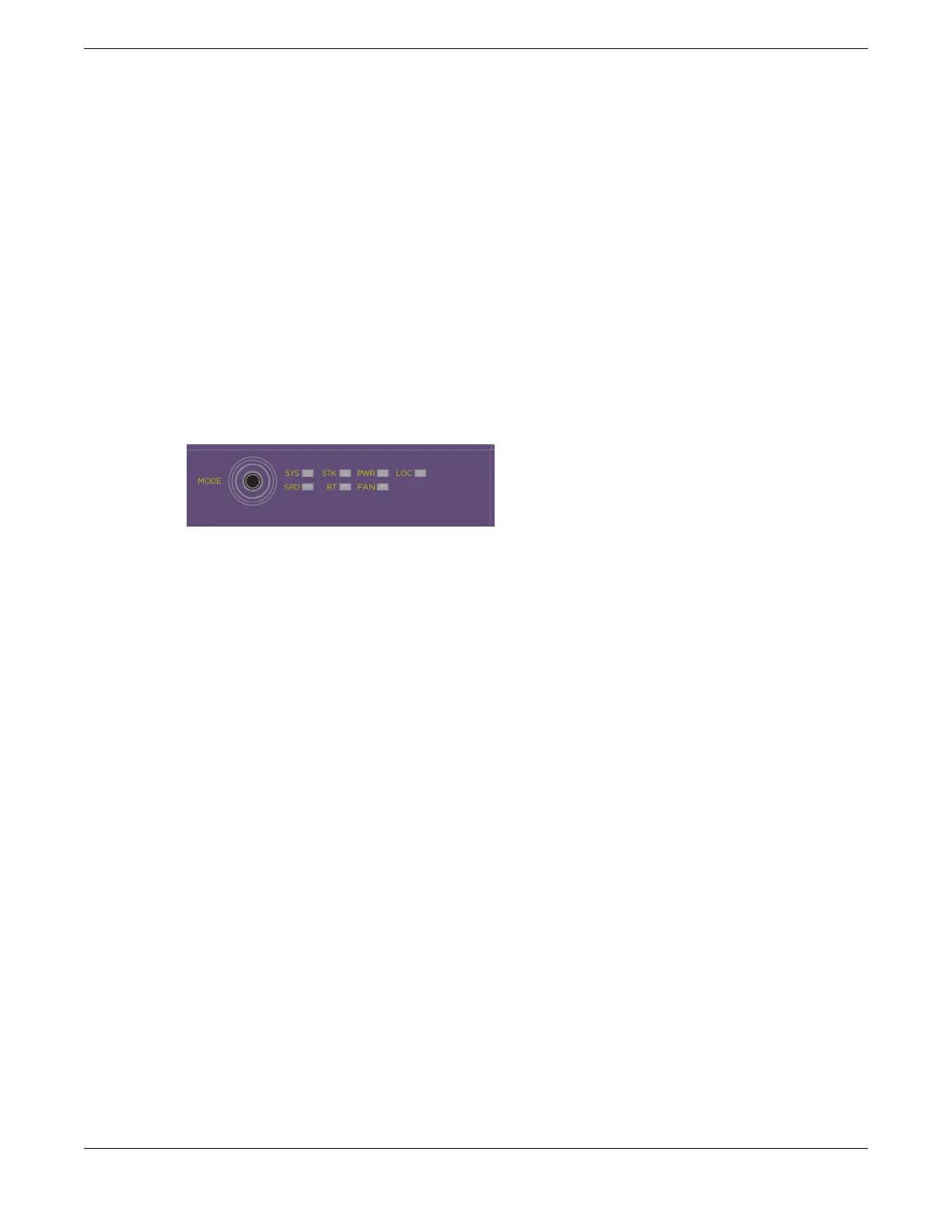
The Mode button is used to cycle through three display modes for the port LEDs.
After two presses of the Mode button, the port LEDs will enter the STK Display Mode,
indicated by the STK LED. STK mode is used to indicate slot presence and slot number
via the rst eight port LEDs.
Figure 23: Mode Button with STK LED Example
The LED is steady green if the link is OK, blinking green if trafc is present, and off if no
signal is present.
A quick way to verify that the cable connections match the software conguration is
to check the stack number indicator on each switch. If the slot numbers do not line
up in the order you arranged the switches, this might indicate that the stacking cable
setup differs from what you intended when you congured the software. In this case,
reconnect the cables in the correct order and perform the software conguration again.
Primary/Backup Switch Redundancy
When your stack is operational, one switch is the primary switch, responsible for
running network protocols and managing the stack.
To provide recovery in case of a break in the stack connections, you can congure
redundancy by designating a backup switch to take over as primary if the primary
switch fails. When you perform the initial software conguration of the stack, the
“easy setup” conguration option automatically congures redundancy, with slot 1 as
the primary and slot 2 as the backup. You can also congure additional switches as
“primary-capable,” meaning they can become a stack primary in case the initial backup
switch fails.
When assigning the primary and backup roles in mixed stacks, consider the feature
scalability and the speed of each switch model. The easy setup conguration process
selects primary and backup switches based on capability and speed. The following list
shows the capabilities based on the ability to cross stack with other switch families. The
most capable switches are shown at the top of each list:
Build Stacks Build Basic Stacks
ExtremeSwitching 5320 Series Hardware Installation Guide 43

 Loading...

