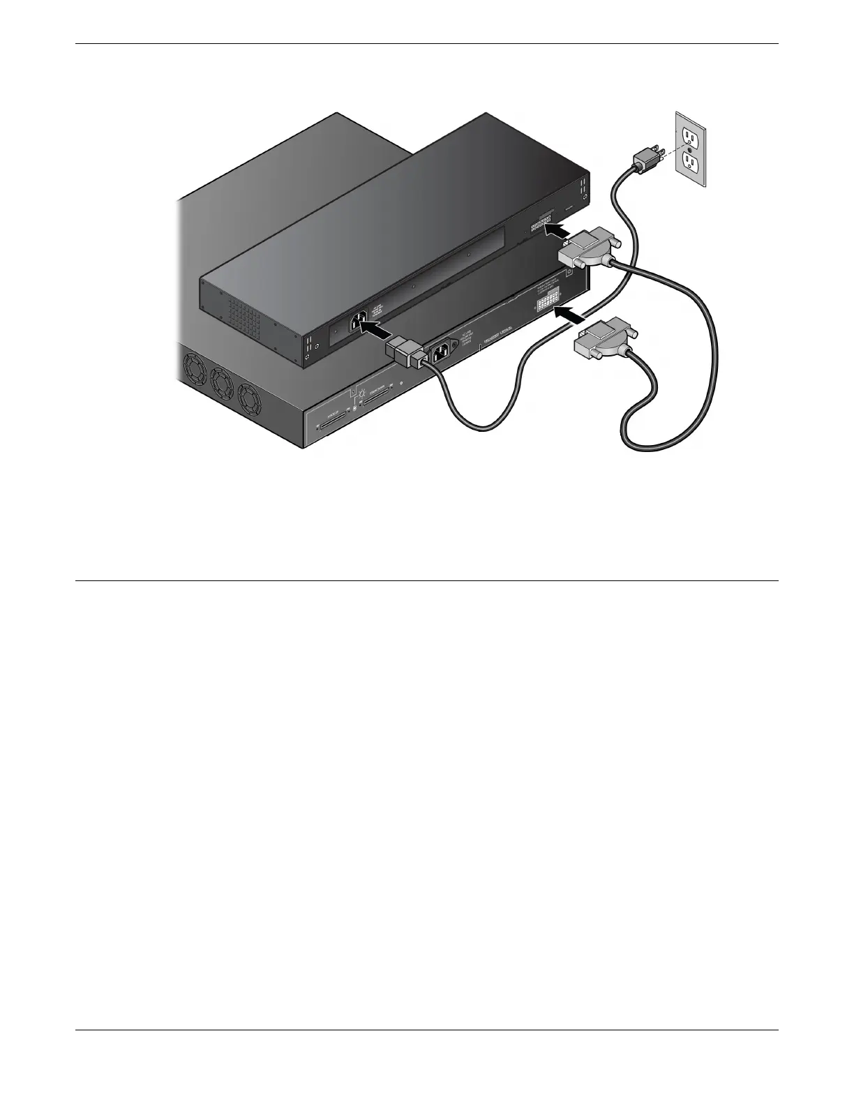
Figure 59: RPS cable and AC Power Cord Connection
The AC power LED on the rear of the RPS turns green to indicate a successful
connection and that the RPS is operating properly.
Connect Network Interface Cables
About This Task
Use the appropriate type of cable to connect the ports of your switch to another switch
or router. Refer to the Extreme Optics website for descriptions of optics and cables, as
well as a complete list of supported cable lengths, and a list of the cable types that are
compatible with your equipment.
Working carefully, one port at a time, do the following:
Procedure
1. Verify that you have identied the correct cable for the port.
2. Use an alcohol wipe or other appropriate cleaning agent to clean the cable
connectors; make sure they are free of dust, oil, and other contaminants.
3. If you are using optical ber cable, align the transmit (Tx) and receive (Rx) connectors
with the correct corresponding connectors on the switch or the I/O module.
4. Press the cable connectors into their mating connectors on the switch or I/O module
until the cable connector is rmly seated.
5. Repeat the preceding steps for the remaining cables on this or other switches or I/O
modules.
6. Dress and secure the cable bundle to provide appropriate strain relief and protection
against bends and kinks.
Install Your Switch Connect Network Interface Cables
ExtremeSwitching 5320 Series Hardware Installation Guide 77

 Loading...

