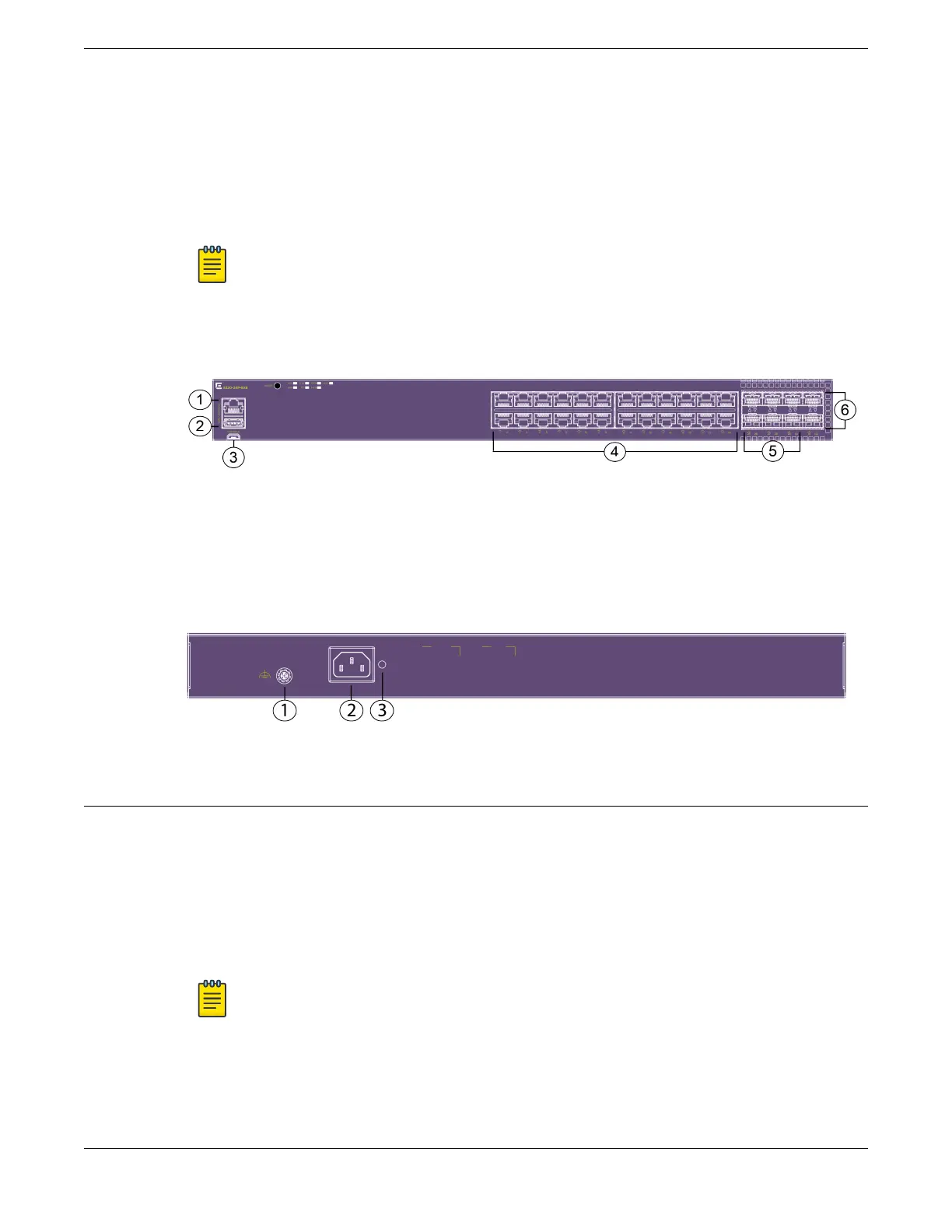
1 = Serial console port (RJ-45)
2 = USB Type-A port
3 = USB Micro-B console port
4 = 24 x 10/100/1000BASE-T (autosensing) MACsec capable ports with 802.3at Type 2
PoE (30W)
Note
The 10/100 ports support half duplex; the 1000 port supports full duplex. Half-
duplex is not supported on these ports when operating at 1Gbps.
5 = 6 x 1/10Gb SFP MACsec capable uplink ports
6 = 2 x 10Gb SFP+ Universal Ports/stacking ports
Figure 7: 5320-24P-8XE Front Panel
The rear panel of the switch includes:
1 = Grounding lug
2 = AC power inlet connector
3 = Cable tie mount for power cord management
Figure 8: 5320-24P-8XE Rear Panel
5320-16P-4XE Switch Features
The front panel of the switch includes:
1 = Serial console port (RJ-45)
2 = USB Type-A port
3 = USB Micro-B console port
4 =16 x 10/100/1000BASE-T (autosensing) MACsec capable ports with 802.3at Type 2
PoE (30W)
Note
The 10/100 ports support half duplex; the 1000 port supports full duplex. Half-
duplex is not supported on these ports when operating at 1Gbps.
5 = 2 x 1/10Gb SFP MACsec capable uplink ports
6 = 2 x 10Gb SFP+ Universal Ports/stacking ports
ExtremeSwitching 5320 Series Overview 5320-16P-4XE Switch Features
ExtremeSwitching 5320 Series Hardware Installation Guide 17

 Loading...

