5. Repeat step 4 for the right side of the switch.
6. Mount the switch under the table by screwing a provided wood screw through
each hole in the mounting ears into the anchors. Ensure that all screws are securely
fastened and that the switch is rmly attached to under the table.
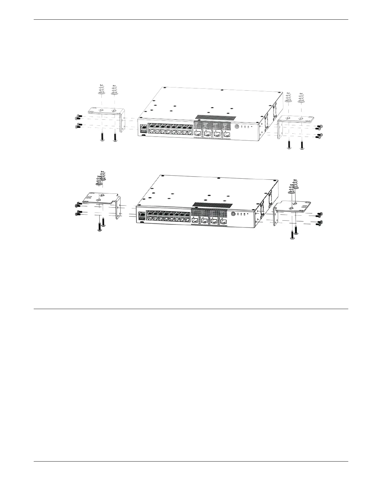
Figure 50: Under the Table Mount: Attaching 1U mounting ears to 5320-16P models
Figure 51: Under the Table Mount: Attaching larger mounting ears to 5320-16P
models
There is a "cleaner" method of attaching the mounting ears to the switch so that they
are tucked under the switch instead of pointing away from the switch. Figure 49 on
page 70 illustrates attaching the mounting ears so that they are underneath the switch.
Install an External Redundant Power Supply
The RPS-150W-XT redundant power supply (RPS) can be installed on a at surface, or in
a 19-inch rack using the included two-post rack mount kit (XN-2P-RMKIT-003).
Install the RPS on a Flat Surface
Four self-adhesive rubber pads are provided for installing at surfaces, like a table. The
pads keep the RPS from scratching the supporting surface and help ensure adequate
airow around the RPS.
To install an RPS on a table - or any rm, at surface - follow these steps.
1. Carefully separate the four rubber pads that are provided
2. Apply the pads to the underside of the RPS by placing a pad at each corner,
ensuring that all corners are aligned. Figure 52 shows the locations for attaching
the rubber mounting feet on the switch.
Install Your Switch Install an External Redundant Power Supply
ExtremeSwitching 5320 Series Hardware Installation Guide 71

 Loading...

