Slot 1 Slot 2 Slot 3 Slot 4Slot 5
Rack A
Rack B Rack C Rack D Rack E
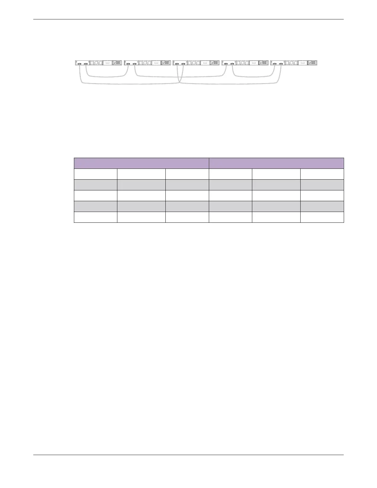
Figure 31: Top-of-Rack Stack Installation
Table 12 lists the recommended order for connecting the stacking ports in this
example.
Table 12: Stacked Switches across Several Racks: Connections
Connect this slot and port . . . . . . To this slot and port
Slot 1 Rack A Port 2 Slot 2 Rack B Port 1
Slot 2 Rack B Port 2 Slot 3 Rack D Port 1
Slot 3 Rack D Port 2 Slot 4 Rack E Port 1
Slot 4 Rack E Port 2 Slot 5 Rack C Port 1
Slot 5 Rack C Port 2 Slot 1 (Rack A Port 1
Connect Your Stack to the Management Network
Before you can congure SwitchEngine for a new stack, your management console
must be connected to at least one switch in the stack.
Connect your management console to a serial console port or the Ethernet
management console port on the switch that will become the stack primary node.
If you plan to congure redundancy, connect to the console ports of all switches in the
stack that will be primary-capable.
If you followed the cabling examples in Connect the Switches to Form the Stack Ring
on page 55, and if you use the Easy Setup conguration procedure, only slots 1 and
2 can become the primary node. However, you can connect all switch management
ports in the stack if you choose to do so. There is an alternate IP address conguration
that will enable you to log in directly to each switch in the stack through its Ethernet
management port.
See the
SwitchEngine User's Guide
for your version of SwitchEngine for instructions to
perform the software conguration for your stack.
Connect Your Stack to the Management Network Build Stacks
58 ExtremeSwitching 5320 Series Hardware Installation Guide

 Loading...

