IN1806 and IN1808 Series Scaling Presentation Switchers • Installation 15
F
DTP2/XTP/HDBT output connector (output 1B) — This connector and the HDMI
output connector (1A) are mirrored, meaning that they display the same image (see
figure 3 on page 12 and figures 4 through 6 on page 13).
• Connect a DTP or DTP2 receiver, an XTP matrix switcher, or an
HDBaseT-compatible receiver to this RJ-45 twisted pair Out connector. For cable
wiring and recommendations, see Twisted Pair Recommendation for DTP, XTP,
and HDBaseT Connectors on page 22.
• This output also allows for remote powering of DTP and DTP2 receivers, as well
as over-DTP analog audio which matches the 5-pole analog audio output of the
receiver.
• To transmit or receive infrared data to and from a sink connected to
the DTP/DTP2/HDBaseT receiver or XTP matrix, connect a control
device to the 3-pole IR Over TP captive screw port (see
G
Over TP
IR pass-through port on the next page).
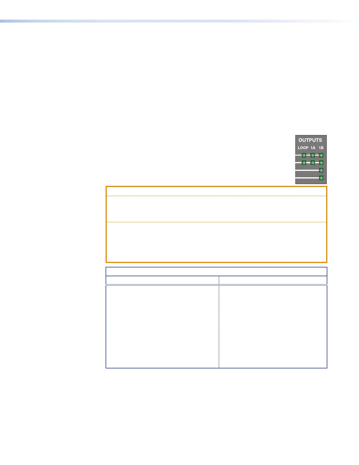
The output 1B connector corresponds to the following front panel LEDs (see the
illustration at right):
• Signal LED — Lights when the scaler is sending a signal.
• Link LED — Lights when a valid link is established.
ATTENTION:
• Do not connect this connector to a computer or telecommunications network.
• Ne connectez pas ce port à des données informatiques ou à un réseau de
télécommunications.
• DTP remote power is intended for indoor use only. No part of the network that
uses DTP remote power should be routed outdoors.
• L’alimentation DTP2 à distance est exclusivement réservée à un usage en
intérieur. Un réseau utilisant une alimentation à distance ne peut pas être routé
en extérieur.
Signal Support
DTP Mode XTP Matrix and HDBaseT Mode
• HDCP-compliant digital video
• Embedded audio into the TMDS output
or analog audio
• DTP standard IR pass-through signals
on the associated 3-pole captive screw
connector
• Ethernet insertion of RS-232 control
signals (see RS-232 and IR Signal
Insertion on page 47)
• Remote power to a DTP receiver
• HDCP-compliant digital video
• Embedded audio into the TMDS
output
• IR pass-through signals on the
associated 3-pole captive screw
connector
• Ethernet insertion of RS-232 control
signals (see RS-232 and IR Signal
Insertion)