IN1806 and IN1808 Series Scaling Presentation Switchers • Installation 16
G
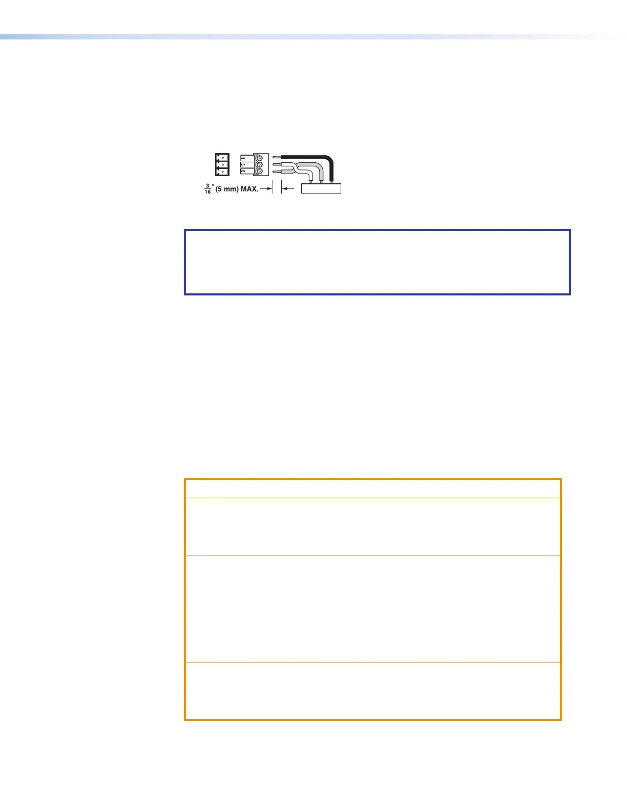
Over TP IR pass-through connector — To transmit or receive infrared data to and
from a sink connected to a DTP or DTP2 receiver, XTP matrix, or HDBaseT display,
connect a control device to the 3-pole Over TP IR captive screw port (see figure 3
on page 12 and figures 4 through 6 on page 13). Figure 7 shows how to wire the
connector.
RxTx
RxTx
G
G
IR
, Rx, and G Pins
Figure 7. Wiring the Over TP IR Connector
NOTE: RS-232 communication can also be sent to the far end of the twisted
pair connection, but it must be done through RS-232 insertion via Ethernet. A
control signal applied to an IN1806 or IN1808 Series LAN or AV LAN port can be
routed to the RS-232 port of any connected twisted pair device (see Ethernet to
RS-232 Insertion on page 48).
H
Analog audio line input connectors 3 and 4 — Connect line level analog audio
sources to audio input connectors 3 and 4 on the 5-pole captive screw connector
for balanced or unbalanced stereo audio (see figure 3 and figures 4 through 6).
Connectors are included with the unit, but the audio cable is not (see figure 10 on
page 19 for wiring).
I
Analog audio Mic/Line input connectors 1 and 2 — Connect balanced or
unbalanced mic or line level inputs to these 3-pole Mic/Line captive screw connectors
These inputs support optional +48 VDC phantom power, which is indicated by the LEDs
at the left of the connectors.
J
Analog audio line output connectors 1 through 4 — Connect balanced or
unbalanced analog audio output devices to one or both 5-pole captive screw audio
output connector pairs 1 and 2 or 3 and 4 (see Analog Audio Connections on
page 19).
ATTENTION:
• For unbalanced audio, connect the sleeves to the ground contact. Do not
connect them to negative (–) contacts.
• Pour l’audio asymétrique, connectez les manchons au contact au sol. Ne
PAS connecter les manchons aux contacts négatifs (–).
• The length of the exposed wires in the stripping process is critical. The ideal
length is 3/16 inch (5 mm). If the exposed portion is longer, the wires may
touch, causing a short circuit between them. If the exposed wires are shorter,
they can be easily pulled out, even if tightly fastened by the captive screws.
• La longueur des câbles exposés est primordiale lorsque l’on entreprend
de les dénuder. S’ils sont un peu plus longs, les câbles exposés pourraient
se toucher et provoquer un court circuit. S’ils sont un peu plus courts, ils
pourraient sortir, même s’ils sont attachés par les vis captives.
• Do not tin the wires. Tinned wire does not hold its shape and can become
loose over time.
• Ne pas étamer les câbles. Les câbles étamés ne sont pas aussi bien fixés
dans les terminaisons des connecteurs à vis captives et pourraient sortir.
7