IN1806 and IN1808 Series Scaling Presentation Switchers • Installation 17
K
LAN connector (IN1806 and IN1808 base model only) — To control the IN1806 and
the IN1808 base model through Ethernet, connect a LAN or WAN to this RJ-45 LAN
connector (see figure 3 on page 12 and figures 4 through 6 on page 13). Ethernet
control allows you to configure and control the scaler from a remote location via SIS
commands, the PCS software, or the embedded web pages.
NOTE: For the IPCP models, connect a LAN or WAN to any of the AV LAN
connectors or to the LAN connector on the IPCP Pro control processor (see
Q
on
the next page).
L
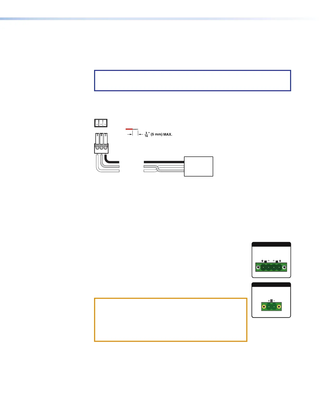
Remote RS-232 connector — Connect a host device to this 3-pole captive screw
connector for RS-232 serial control of the scaler (see figure 3 and figures 4 through
6). The default baud rate is 9600.
Do not tin the wires!
Controlling
Device
Ground (G)
Receive (Rx)
Transmit (Tx)
Ground (G)
Receive (Rx)
Transmit (Tx)
Bidirectional
Tx Rx G
Figure 8. RS-232 Wiring
M
Reset LED — This green LED remains lit while the IN1806 and IN1808 Series has
power (see figure 3 and figures 4 through 6). While the Reset button (see
N
, below)
is being pressed and held, this LED blinks every 3 seconds to indicate the level of reset
initiated if the button is released at that point (see Reset Modes on page 46 for more
information).
N
Reset button — This recessed button initiates levels (modes) of reset on the
IN1806 and IN1808 Series. To initiate the different reset levels, use a pointed object
such as a small Philips screwdriver or a stylus to press and hold the button while the
scaler is running or while it is being powered up (see Reset Modes).
O
Amplified audio output connector (see figures 4 through 6) —
• IN1808 IPCP SA — Connect unpowered speakers,
4-ohm @ 50 watts or 8-ohm @ 25 watts, to the 4-pole Amplified
Output connector (shown at right) to play amplified stereo audio.
• IN1808 IPCP MA 70 — Connect unpowered, high impedance
speakers to the 2-pole Amplified Output connector (shown at
right) to play amplified mono audio.
ATTENTION:
• Ensure the rated input voltage of the speakers matches the
rated output voltage of the IN1806 or IN1808.
• Assurez-vous que la tension nominale d’entrée des
enceintes soit compatible avec la tension nominale de
sortie du IN1806 ou IN1808.
P
Aux line audio input connector — Connect a line level analog audio source to this
5-pole captive screw connector for balanced or unbalanced mono or stereo audio (see
figure 3 and figures 4 through 6). The Aux input is shared and can be associated with
one or more video inputs (see Analog Audio Connections on page 19).
8
2x25W(8Ω)/2x50W(4Ω)
L
R
CLASS 2 WIRING
AMPLIFIED OUTPUT
AMPLIFIED OUTPUT
70V - 100W
CLASS 2 WIRING