XTP CrossPoint Series • Installation 15
3
LAN (Ethernet connectors — As desired, connect a TP cable between a host
device or control LAN and this connector for passive extension to the LAN (Ethernet
connector on the connected endpoint (see TP connectors on page 19 to wire
the connector).
4
IR/RS-232 Over XTP connectors — If desired, connect serial RS-232 signals,
modulated IR signals, or both to these 3.5 mm, 5-pole captive screw connectors
for bidirectional RS-232 and IR communications on the associated inputs (see
RS-232 and IR connectors on page 22 to wire the connectors).
XTP CP 4i Fiber 4K (fiber optic input board)
SIGLINK
XTP IN
LANLAN LANLAN
SIG LINK
XTP IN
SIGLINK
XTP IN
SIGLINK
XTP IN
OVER FIBER
XTP CP 4i FIBER 4K
RS-232
IR
Tx Rx GTxRx
RS-232
IR
Tx Rx GTxRx
RS-232
IR
Tx Rx GTxRx
RS-232
IR
Tx Rx GTxRx
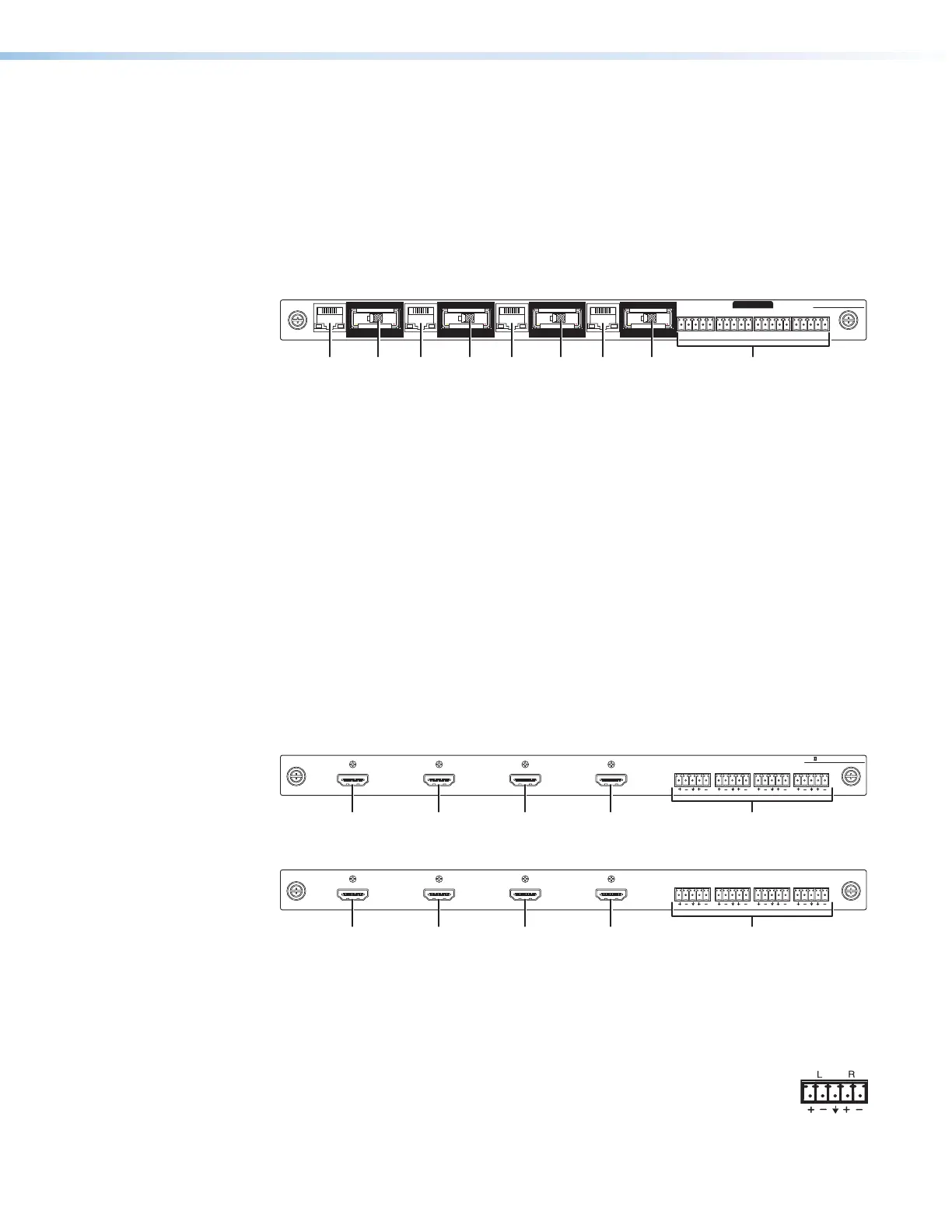
Figure 5. Fiber Optic Input Board Connectors and Indicators
1
XTP In connectors — Connect a fiber optic cable between the Tx connector
on a compatible Extron fiber optic transmitter and this connector. This board
uses small form factor pluggable (SFP) modules with industry-standard LC fiber
optics connectors to provide reliable physical connectivity and precise fiber core
alignment.
Signal LED — Indicates that a cable is connected to a fiber optic transmitter.
Link LED — Indicates that a valid fiber optic signal is detected.
2
LAN (Ethernet) connectors — As desired, connect a TP cable between a
host device or control LAN and this connector for passive extension to the LAN
(Ethernet) connector on the connected endpoint (see TP connectors on page
19 to wire the connector).
3
IR/RS-232 Over Fiber connectors — If desired, connect serial RS-232 signals,
modulated IR signals, or both to these 3.5 mm, 5-pole captive screw connectors
for bidirectional RS-232 and IR communications on the associated inputs (see
RS-232 and IR connectors on page 22 to wire the connectors).
XTP II CP 4i 4K PLUS and XTP CP 4i HDMI (HDMI input boards)
AUDIO
LR LR LR LR
INPUTS
XTP II CP 4i HD 4K PLUS
11 1111 11 22
Figure 6. 4K HDMI Input Board Connectors
XTP CP 4i HDMI
AUDIO
LR LR LR LR
IN
Figure 7. HDMI Input Board Connectors
1
Input connectors — Connect an HDMI cable between this port and the HDMI
output port of the digital video source (see HDMI connectors on page 22 for
pin assignments and to use the LockIt HDMI Cable Lacing Bracket to secure the
connector to the transmitter).
2
Audio Inputs (analog audio) connectors — Connect balanced or
unbalanced stereo audio inputs to these 3.5 mm, 5-pole captive screw
connectors (see Analog audio input connectors on the page 24 to
wire the connectors).