XTP CrossPoint Series • Installation 16
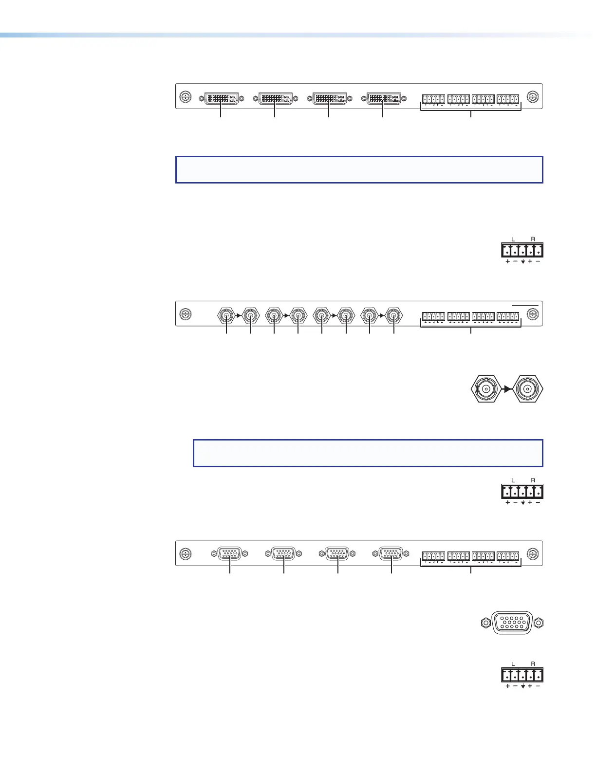
XTP CP 4i DVI Pro (DVI Pro input board)
XTP CP 4i DVI Pro
AUDIO
LR LR LR LR
IN
Figure 8. DVI Pro Input Board Connectors
NOTE: Although the DVI Pro boards use DVI-I connectors, the matrix switchers
handle only DVI-D (digital) video.
1
Input connectors — Connect a DVI cable between this port and the DVI output
port of the digital video source (see DVI connectors on page 23 for pin
assignments).
2
Audio inputs (analog audio) connectors — Connect balanced or
unbalanced stereo audio inputs to these 3.5 mm, 5-pole captive screw
connectors (see Analog audio input connectors on page 24 to wire
the connectors).
XTP CP 4i 3G-SDI (3G/HD-SDI/SDI input board)
AUDIO
LR LR LR LR
IN
XTP CP 4i 3G-SDI
LOOP OUTINPUTLOOP OUTINPUTLOOP OUTINPUTLOOP OUTINPUT
Figure 9. 3G Input Board Connectors
1
Input connectors — Connect a 3G-SDI, HD-SDI, or SDI video
input to this BNC connector. The board also accepts embedded
digital audio on this port.
2
Loop Out connector — Connect a local digital display to this BNC connector for
a buffered loop-through on the input signal.
NOTE: The board ships with 75 ohm terminators on the Loop Out connectors.
Extron recommends leaving these installed when the loop out is not used.
3
Audio inputs (analog audio) connectors — Connect balanced or
unbalanced stereo audio inputs to these 3.5 mm, 5-pole captive screw
connectors (see Analog audio input connectors on page 24 to wire
the connectors).
XTP CP 4i VGA (VGA Input board)
XTP CP 4i VGA
AUDIO
LR LR LR LR
IN
Figure 10. VGA Input Board Connectors
1
Input connectors — Connect a VGA cable between this port
and the analog video output port of the digital video source (see
Analog video connectors on page 23 for pin assignments and
non-RGB video formats).
2
Audio Inputs (analog audio) connectors — Connect balanced or
unbalanced stereo audio inputs to these 3.5 mm, 5-pole captive screw
connectors (see Analog audio input connectors on page 24 to wire
the connectors).