XTP CrossPoint Series • Installation 17
B
Output boards space —
NOTE: See figure 2 on page 12 and figure 3 on page 13.
Install output boards as desired in output slots 1 through 4 (XTP CrossPoint 1600),
slots 1 through 8 (XTP CrossPoint 3200) and make connections. See Installing the
Input or Output Board or Blank Panel on page 147 and the individual board
descriptions below.
NOTE:
• Install blank panels in unused slots to ensure proper ventilation.
• XTP CrossPoint 3200: To ensure reliable operation, it is recommended that
unused output slots (especially slots 5 through 8) be populated with either
active output boards or load boards.
XTP CP 4o and XTP CP 4o 4K (XTP Output board)
OUTPUTS
XTP CP 4o 4K
RS-232
IR
Tx Rx GTxRx
RS-232
IR
Tx Rx GTxRx
RS-232
IR
Tx Rx GTxRx
RS-232
IR
Tx Rx GTxRx
XTP OUT
PWR
LAN
SIG LINK
XTP OUT
PWR
LAN
SIG LINK
XTP OUT
PWR
LAN
SIG LINK
XTP OUT
PWR
LAN
SIG LINK
OVER XTP
11
11 11 1133 33 33 33
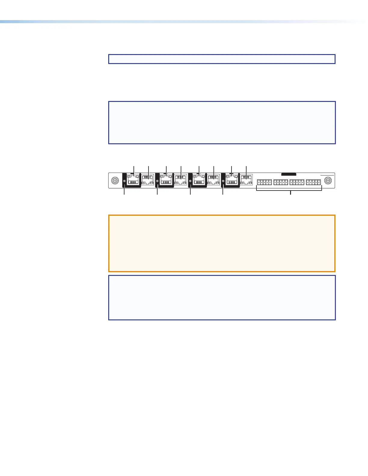
Figure 11. XTP Output Board Connectors and Indicators (XTP CP 4o 4K)
ATTENTION:
• The XTP output board can provide power over XTP (PoX) to connected
devices. PoX is intended for indoors use only. No part of a network that uses
PoX can be routed outdoors.
• La carte sortie XTP peut fournir l’alimentation sur XTP(PoX) aux appareils
connectés. PoX est destiné à une utilisation en intérieur uniquement. Aucune
partie d’un réseau qui utilise PoX ne peut être routée en extérieur.
NOTE: PoX must be enabled using:
• SIS commands (see the applicable XTP Power SIS commands on page 106)
• Built-in HTML pages (see XTP Power Page, on page 143)
• The XTP System Configuration software (see the XTP System Configuration
Software help file, available at www.extron.com)
1
XTP output connectors — Connect an STP cable between this connector and
a compatible Extron XTP receiver (see TP connectors on page 19 to wire the
connector).
2
XTP Power indicators — Lights to indicate that the output board is providing
power over XTP (PoX) to the receiver connected to this RJ-45 connector.
3
LAN (Ethernet) connectors — As desired, connect a TP cable between a
host device or control LAN and this connector for passive extension to the LAN
(Ethernet) connector on the connected endpoint (see TP connectors on
page 19 to wire the connector).
4
IR/RS-232 Over XTP Connectors — If desired, connect serial RS-232 signals,
modulated IR signals, or both to these 3.5 mm, 5-pole captive screw connectors
for bidirectional RS-232 and IR communications on the associated outputs (see
RS-232 and IR connectors on page 22 to wire the connectors).