Chapter 9 Fieldbus I/O Interfaces
PAGE 9-28
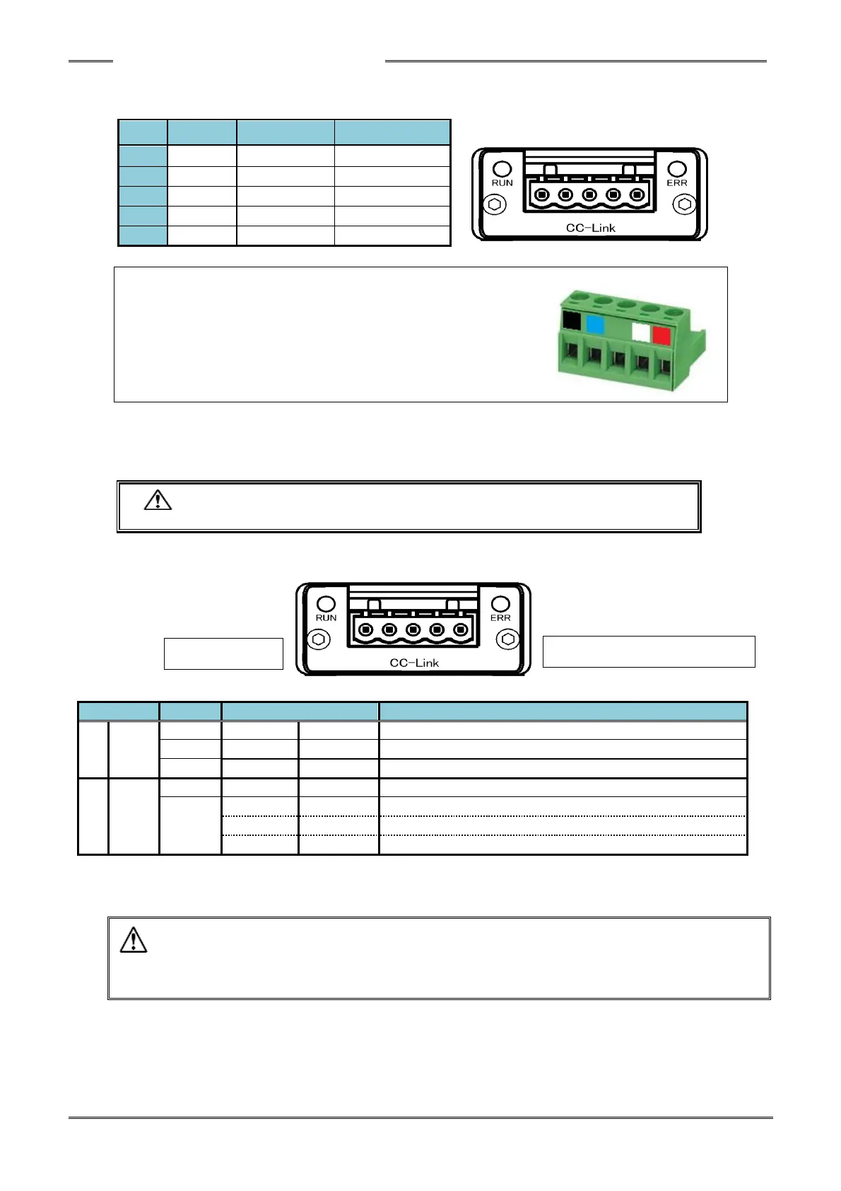
● Module Pin Configuration
Manufacturer: Phoenix Contact
Type: Connector plug
Model: MSTB 2.5/5-ST-5.08 AU M
Applicable wire size: AWG 14 ~ 23 or 0.25mm
2
~ 2.5mm
2
* The connector is provided with the equipment.
The cable supplied by customer
However, the compatible wire size and recommended rod terminals (ferrules) are as follows.
・ Compatible wire size ・・・ AWG 14 ~ 23 (0.25mm
2
~ 2.5mm
2
)
・ Recommended rod terminals (ferrules)
・・・ Model: AI 2,5-6 WH (Phoenix Contact)
・ Be sure to connect the cable with all power OFF.
The module LEDs indicate the node status of the HFC3000 CC-Link System and the network state.
● List of LED Indications
Power is not supplied or connection is not established.
A critical error has occurred.
A critical error has occurred.
A cyclic redundancy check (CRC) error has occurred.
Station No. or baud rate setting is changed after power on.
・ Even though no problem is indicated by the CCLINK LED (ex. RUN LED: green Lits on, ERR
LED:off), if the PLC CCLINK configuration does not match the Fieldbus setup that is setup
in the HFC controller, the HFC3000 CC-LINK system can not communicate. Confirm I/O
size, Occupied Station number , Cyclic settings, etc. all match) (PAGE9-16)