Chapter 4 Installation and Wiring
PAGE 4-18
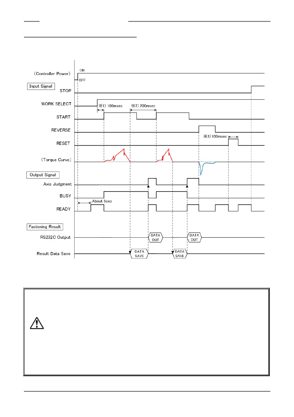
4-5-5 Input/output signal timing chart
●Basic control signals (Controller firmware ver. 1.304 or later)
*1) WORK SELECT requires a response time of 100 msec or more after the READY signal
(ON) is output until the START signal is input.
*2) After the fastening operation completes, a wait time of 200 msec or more is required to
input the next START signal. If the START signal is continually input, another cycle
cannot be performed (until the START signal transitions to OFF one time).
*3) An input time of 100msec or more is required for the RESET signal or the STOP signal.
If the signal is continually input, another cycle cannot be performed.
*4) When the Data Save operation completes, the RS232C data communication output is
performed only once for approximately 90 msec. (Before firmware ver. 1.303, the
RS232C data output is performed after the fastening operation is complete)
To acquire the fastening result data to a PC, start the communication by the START
signal input timing (BUSY signal ON).