Chapter 4 Installation and Wiring
PAGE 4-20
4-6 External Monitoring Device Signal
This auxiliary connector is used to output Torque, Angle, Current & Speed signals to external equipment
for monitoring purposes (X-Y Plotter, etc). The signals output from this connector are the same signals
that the system receives during the fastening process. This connection is not required for the system to
operate.
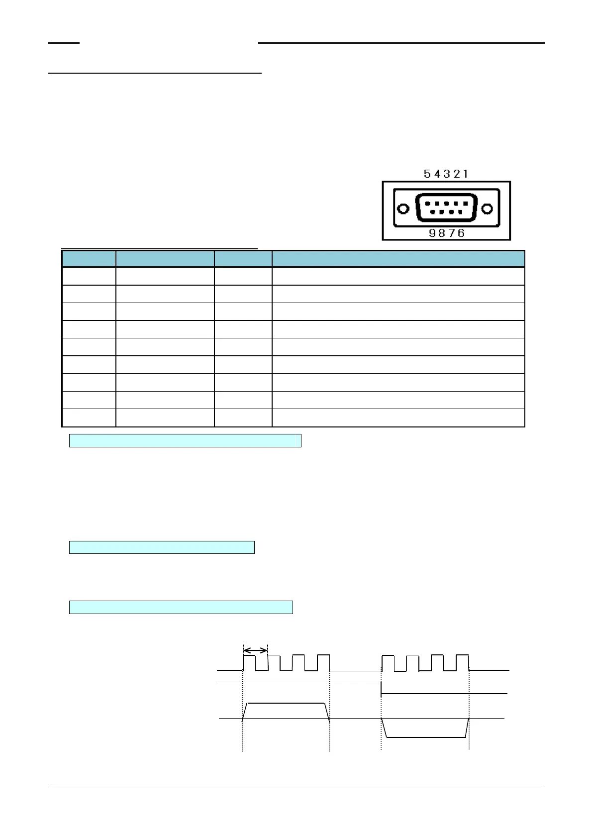
Compatible connector
D-SUB 9-pin plug Inch thread (#4-40)
External monitor signal specifications
TORQUE OUT: Torque Analog Voltage Signal
Monitoring voltage is indicated from zero torque to full scale torque and the potential difference is
3.7V. The zero voltage is the voltage when the tool is unloaded (nothing connected to the output
shaft and no torque applied).
※The zero voltage is not 0V.(Origin voltage range: -0.4V~+0.4V)
In addition, the zero voltage of each tool may vary even for the same type of tool.
(Ex: If the zero voltage is -0.3V and the voltage at full scale torque is +3.4V, the voltage change is
⊿3.7V.)
ANGLE PULSE: Angle Pulse Signal (5V TTL signal)
Angle pulse will output one pulse for one degree of rotation (at tool output square drive)
※This may differ from the actual rotation angle
(The range of pulses when rotating the end of the tool once is 358~362pulses.)
ANGLE CW/CCW Rotation Direction Signal (5V TTL signal)
Signal is output “high” when the motor is rotating in the normal CW direction and “low” signal when
the motor is rotating in CCW (reverse) direction.