AN6000 Series Optical Line Terminal Equipment Hardware Description
Table 9-9 Components on the PDP (3000068) Connector Panel (Continued)
Connector & Jumper Pin Description
JP1
JP1 is the jumper pin for selecting the working status
indicator LED of the PDP. It can be set in either of the
following two ways:
u When pin1 and pin2 of JP1 are shorted, the green
indicator at the cabinet top indicates the power status of
the PDP.
u When pin2 and pin3 of JP1 are shorted (factory default),
the green indicator at the cabinet top is controlled by the
CALL (order wire call) signal.
XS3
Power supply lightning protection module socket
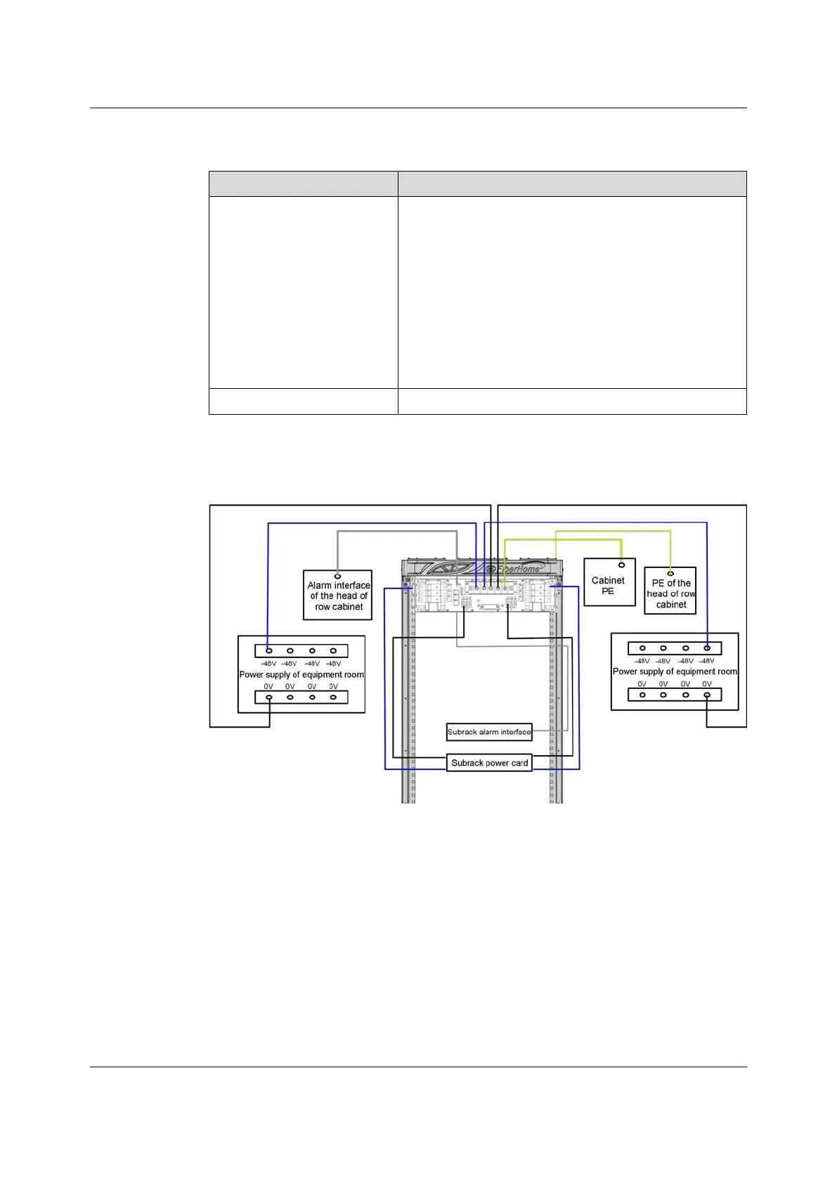
9.4.4 Connection
Figure 9-13 Cable Connections for the PDP (3000068)
9.4.5 Lightning Protection Module
Material Number
3578403R2A
128
Version: B
 Loading...