9 PDPs
Table 9-5 Components of the PDP (3000064) with the Extended Sub-Model 1FH or 2FH
(Continued)
Connector & Jumper Pin Description
XP1 to XP4 Alarm cascade connectors
XP6 Alarm connector for the head of row cabinet
XP7
Alarm connector for indicator LEDs on the top of
cabinet
XS15, XS16
Power supply lightning protection module sockets
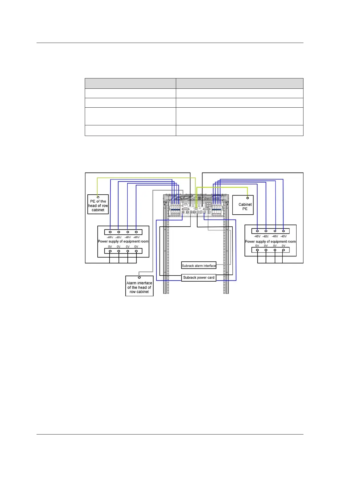
9.3.4 Connection
Figure 9-8 Connections of the PDP (3000064) - Eight Branch Switches
9.3.5 Lightning Protection Module
Material Number
3578403R2A
Failure Indicator LEDs
The lightning protection module is equipped with a failure indicator LED. When the
module works normally, the LED is extinguished, when the modules fails to work,
the LED is illuminated in red.
Version: B
121
 Loading...