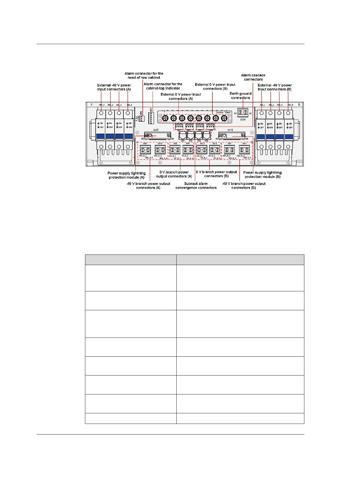
Figure 9-7 Connectors of the PDP (3000064) with the Extended Sub-Model 1FH or 2FH
Table 9-5 describes the components of the PDP (3000064) with the extended sub-
model 1FH or 2FH.
Table 9-5 Components of the PDP (3000064) with the Extended Sub-Model 1FH or 2FH
Connector & Jumper Pin Description
-48V_1 to -48V_4 in area A, -48V_1 to
-48V_4 in area B
Induct 2 × 4 external -48 V power signals. The
connectors in area A and area B can back up each
other.
Eight connectors on the busbar
0 V external power input connectors. The connectors
in area A and area B can back up each other.
XS14
Two protection earth ground connectors, connecting to
the external earth ground bar and the cabinet
respectively
-48V_A_1 to -48V_A_4 (XS6, XS10)
-48 V branch power rail output connectors,
corresponding to -48V_1 to -48V_4 in area A
-48V_B_1 to -48V_B_4 (XS7, XS11)
-48 V branch power rail output connectors,
corresponding to -48V_1 to -48V_4 in area B
0V_A_1 to 0V_A_4 (XS8, XS9)
0 V branch power rail output connectors,
corresponding to connectors in area A
0V_B_1 to 0V_B_4 (XS12, XS13)
0 V branch power rail output connectors,
corresponding to connectors in area B
XS1 to XS4
Subrack alarm convergence connectors
120
Version: B
 Loading...