AN6000 Series Optical Line Terminal Equipment Hardware Description
u The control module enables configuration of the entire system, collects and
reports statuses, processes protocols, and provides the environment
monitoring serial port, local debugging serial port, out-of-band management
network port, and USB port.
u The switch module switches service data, and provides uplink ports.
u The power module supplies power to each functional module of the card.
u The clock module provides working clock signals for each functional module of
the card.
5.4 Uplink Card
The uplink cards provide uplink ports.
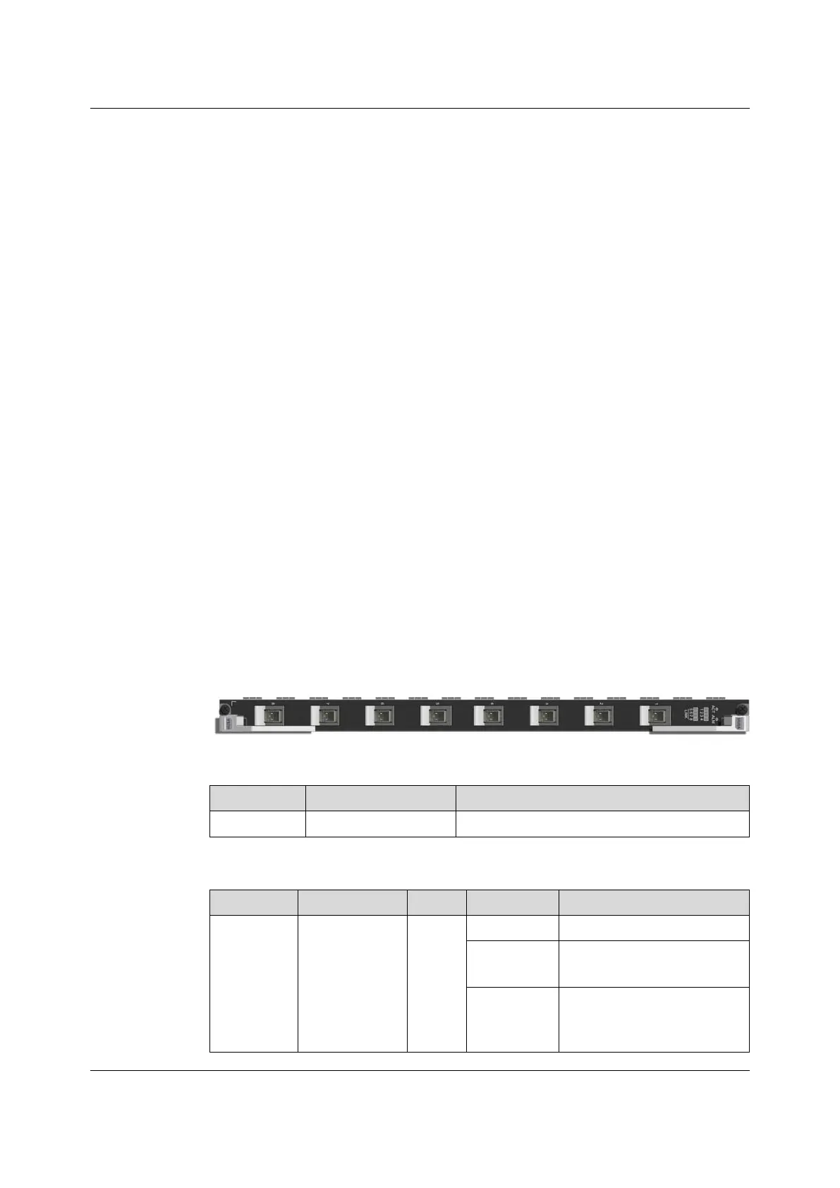
5.4.1 HU8A
Basic Information
Refer to Card Overview for the number, power consumptions, maximum frame
length and weight of the card.
Panel Description
Table 5-4 Interfaces
Identifier
Meaning Description
1 to 8
10GE / GE uplink ports Connect to upper-layer devices.
Table 5-5 Description
Identifier
Meaning
Color Status
Description
ACT
Working
indicator LED
Green
ON
The card is functioning properly.
Blinking
slowly
The card is being initialized.
Blinking
quickly
The card is receiving a
configuration command from
the core switch card.
34
Version: B
 Loading...