Chapter 6: Calibration Procedures
6-5
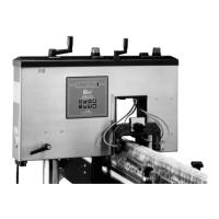
Variable Speed Conveyors
If your FT-70 is installed on a variable speed conveyor line, you
must also install the High Resolution Encoder. The encoder
attaches to the conveyor and sends timing pulses to the FT-70. The
FT-70 uses these timing pulses to synchronize all inspection and
rejection activities with the production conveyor’s speed.
The encoder must be calibrated for each different container type
that is run on the production line.
The following calibration procedures apply only to FT-70 units that
have Baseline Eight of the system software installed. There are
three different procedures depending upon your situation:
• Standard Conveyor Calibration Procedure for standard
conveyors with a 1.5-inch pitch and you know the number of
teeth on the sprocket directly contacting the underside of the
main production transport chain.
• Unknown Sprocket Size Calibration Procedure for standard
conveyors with a 1.5-inch pitch, but you don’t know the
number of teeth on the sprocket directly contacting the
underside of the main production transport chain.
• Non-Standard Conveyor Calibration Procedure for conveyors
that do not have a 1.5-inch pitch, but you do know the number
of teeth on the sprocket directly contacting the underside of the
main production transport chain and the size of the conveyor
segments (chain links).
LED Definitions Quick Reference
The following table defines the LEDs located on the controller
board. For more information on the LED banks refer to Chapter 10:
Controller Board Dip Switch and LED Descriptions.
LED Number S1, B1 S1, B2 S2, B1 S2, B2
1 Diag Error Label 1 Remote Clr Inlabeler 1
2 Reject Pulse Label 2 Broken Slat or Batch Rej Inlabeler 2
3 Hi Res Encoder Label 3 Lw Res Encoder Inlabeler 3
4 Low Foam Label 4 X-ray Enable or Optical FL Inlabeler 4
5 Down Can/Smash Label 5 X-ray Failure or FSR 2 INPUT Inlabeler 5
6 Bulged/High Cap Label 6 Extrn or FSR 1 Cntr Present
7 Missing Cap/Lid Label 7 Slat Backup or Reject Verify System Timing
8 Trigger Label 8 Trigger Trigger
Industrial Dynamics Company, Ltd. © Form 40256-0600