FT-70 Fill Level Inspector Service Manual
8-16
Main Power System Troubleshooting
Power supply instability and failures account for many malfunc-
tions. We recommended testing the power supply voltages as a
starting point when troubleshooting. You need a digital voltmeter
with an impedance of at least 20,000 ohms per volt to perform
these procedures.
Testing the Power Supply
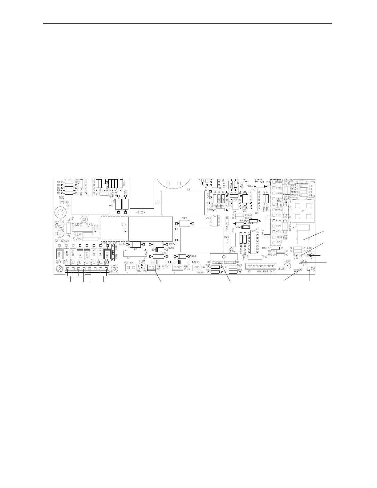
1. Remove the FT-70’s cover to access the power supply inside.
2. Using test point TP3 as ground, test all voltages at the appro-
priate test points.
Figure 8-1. Power Supply Circuit Board test points.
Reference
Test
Point
Output
VDC
Range
VDC
Xfmr
Winding
Source
Supply
Description
1 TP-6 +5 5.0/5.2 28 VAC +V Processor Logic, Scintillation Detector
2 TP-2 +12 11.5/12.5 28 VAC +V Scintillation Tube Pulse Preamplifier,
Control Panel, Serial Port Drivers
3 TP-4 +22 18.0/22.0 28 VAC +V Sensor Emitters/Amplifiers, Input
Comparators
4 TP-5 12 11.5/12.5 28 VAC Unreg Control Panel, Serial Port Drivers
5 J-1 +1000* 800/1200 28 VAC +22VDC Scintillation Detector
6 Q8-3‡ -5 4.9/5.1 28 VAC -12VDC RS232/RS422 Drivers
7 P4-2 +60 50/60 36 VAC Unreg Rejector Driver, Rejector
8 TP-3 Ground
1
4
2
3
8
5
ABCD
7
6
Industrial Dynamics Company, Ltd. © 40256-0600