Chapter 6: Calibration Procedures
6-25
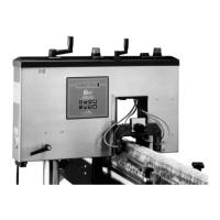
4. You must also remove the FT-70’s cover to access dip switch
pack S1. When performing the calibration procedure you are
required to change the settings for S1-5.
The Line Speed Calibration Procedure
1. Press Key 5 until SYSTEM DISPLAY appears and then press
the Arrow Key to enter the Calibrate Mode. You may be
required to enter a password if your system is password
protected.
2. Press Key 4 until REJECTOR STATUS appears and check to be
sure the rejector is activated. If it is turned off, press the Arrow
Key to turn it on.
3. Open dip switch S1-5.
4. Press Key 5 until REJECTOR TYPE appears and use the Arrow
Key to select the type of Proline rejector installed in your
system.
Note
This procedure is only applicable to systems utilizing a Proline
rejector. If you are using a rejector other than a Proline, you must
use the variable speed production line calibration procedures.
5. Measure the distance in millimeters from the trigger sensor
beam to the centerline of the rejector. Accurate measurement is
extremely important for proper calibration.
6. Press Key 4 until INSPECT TRIG TO C/L REJ appears and use
the Arrow Key to enter the measurement in millimeters.
7. Measure the diameter of a production container (in milli-
meters) at the point where the container intersects the trigger
beam. This is the containers can width at the trigger point.
8. Press Key 5 until CAN WIDTH AT TRIG appears and enter (in
millimeters) the production container’s width at the trigger
point.
9. Measure the diameter of the container (in millimeters) at its
widest point. This is the containers maximum diameter.
10. Press Key 5 until MAXIMUM CAN DIAMETER appears and
enter (in millimeters) the production container’s maximum
diameter.
Industrial Dynamics Company, Ltd. © Form 40256-0600