FT-70 Fill Level Inspector Service Manual
3-24
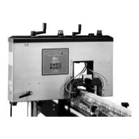
2. Route the AC power cable into the FT-70 through one of the
watertight cable ports located in the bottom of the FT-70.
Figure 3-21. Route the Power Cable into the FT-70.
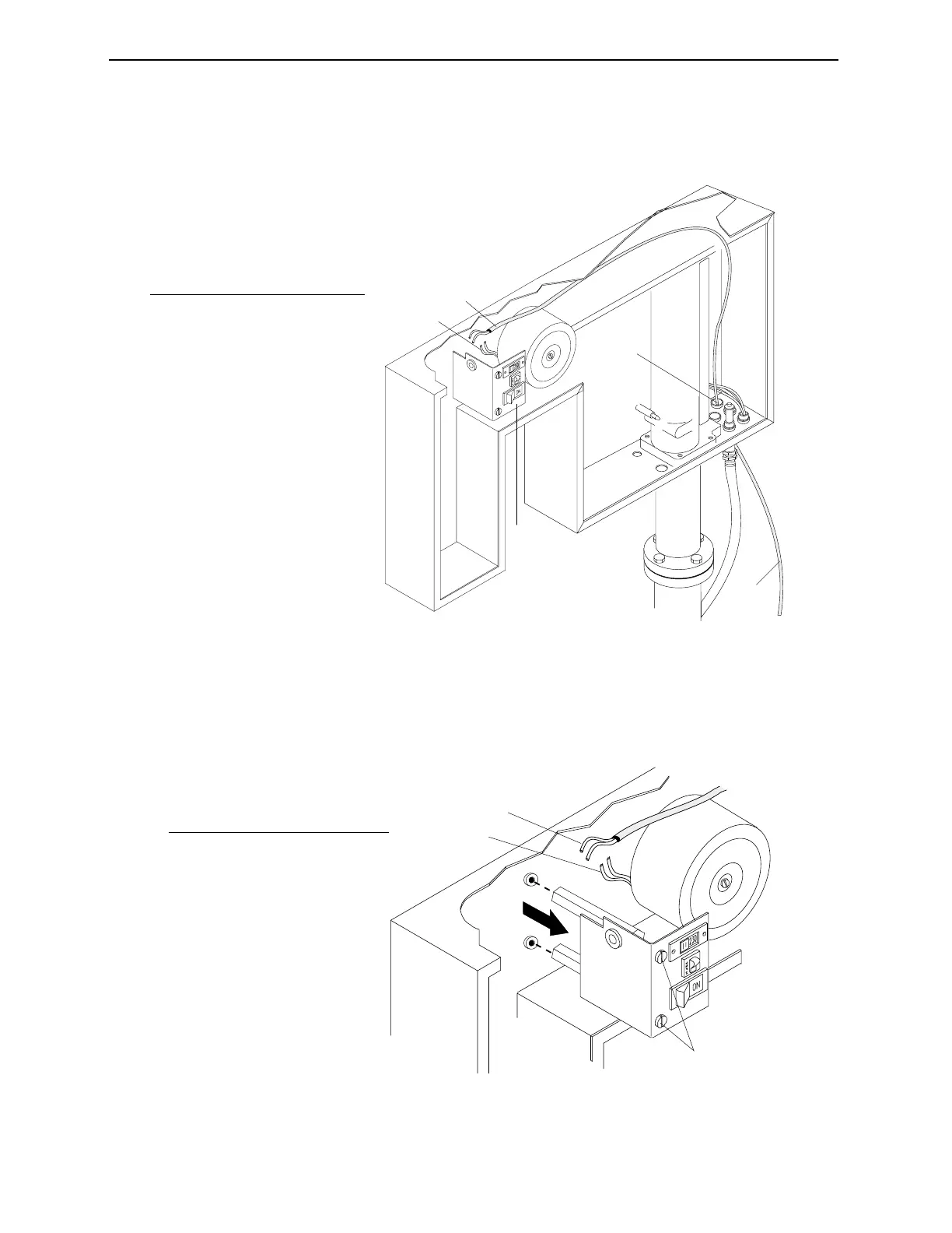
3. Remove the screws securing the power switches bracket and
pull the bracket out to gain access to the power cable wiring.
Figure 3-22. Route the Power Cable into the Power Filter.
1
3
2
4
5
No. Description
1 Power cable
2 Watertight Cable Ports
3 Power Cable Routing
4 Power Filter Wiring
5 Power Switches Bracket
1
2
3
No. Description
1 Remove screws.
2 Main Power Cable Wires
3 Power Filter Wires
Industrial Dynamics Company, Ltd. © 40256-0600