Description
3.7 Cooling
34 Edition 06/2022 A5850-02en
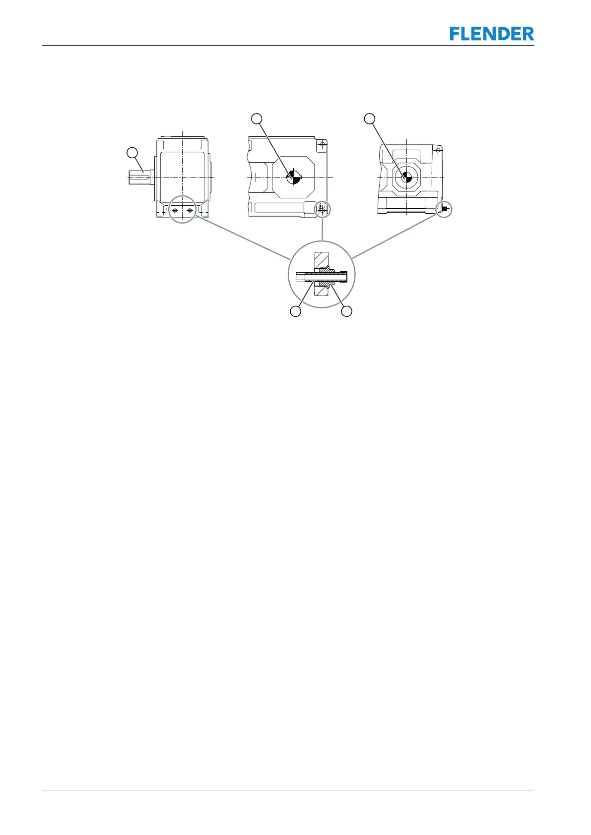
The diagram below shows the cooling coil connections:
Figure3-10:Cooling coil on type K..H and K..M gear units
① Output shaft ③ Cooling water connection
② Reducer screw
Further information
You can find additional information and a detailed illustration of the gear unit and the connec-
tion dimensions in the dimension drawings in the complete gear unit documentation.
The required cooling water flow rate and the maximum permissible inlet temperature can be
found in the separate data sheet, the list of equipment or the dimension drawing in the com-
plete documentation for the gear unit.
3.7.3 Mounted oil supply system3.7 Cooling
Introduction
Depending on the particular contract, the gear unit is equipped with a mounted oil supply
system.
Components of the oil supply system
The mounted oil supply system comprises the following components:
• Pump
• Piping
• Oil filter
• Monitoring devices