Assembly
5.3 Gear unit assembly
68 Edition 06/2022 A5850-02en
Further information
You can find additional information and detailed illustrated description of the threaded holes
in the dimension drawing provided in the complete gear unit documentation.
5.3.7 Mounting the torque arm for the gear unit housing5.3 Gear unit assembly
Introduction
Type K..M gear units have a bore in the input-side housing face for attaching the torque arm.
Design the torque arm according to the relevant restoring force and weight forces.
5.3.7.1 Mounting the torque arm5.3 Gear unit assembly
NOTICE
Damage to the gear unit due to incorrect mounting of the motor and torque arm
Damage to the gear unit due to incorrect mounting of the motor and torque arm is possible
The motor and torque arm may only be mounted after prior consultation with Flender.
Mount the torque arm to the machine side without causing any distortion or deformation.
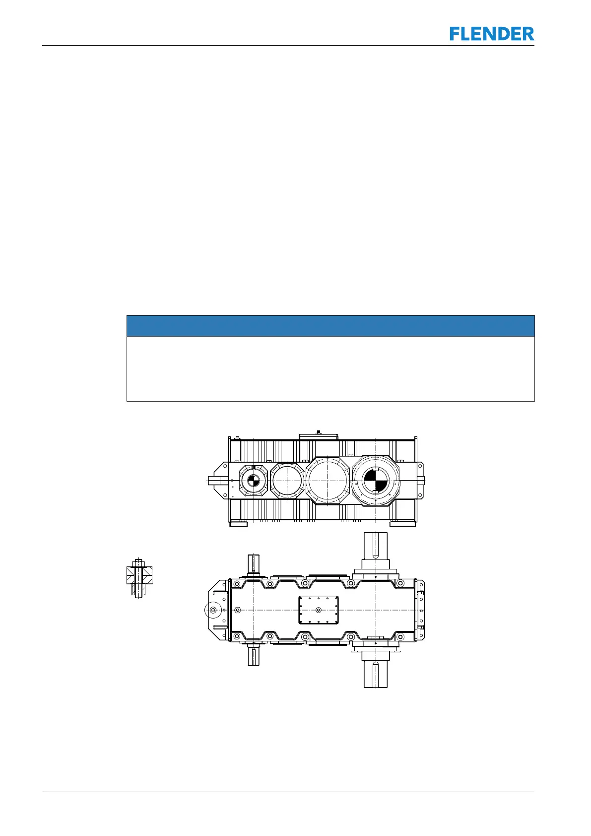
The following diagram shows how a torque arm should be mounted:
Figure5-12:Mounting the torque arm
If you are using a separately installed drive assembly, make sure that no external forces can
act on the gear unit if the assembly is shifted.
Design the torque arm according to the relevant restoring force and weight forces.