Description
3.13 Bearing monitoring
40 Edition 06/2022 A5850-02en
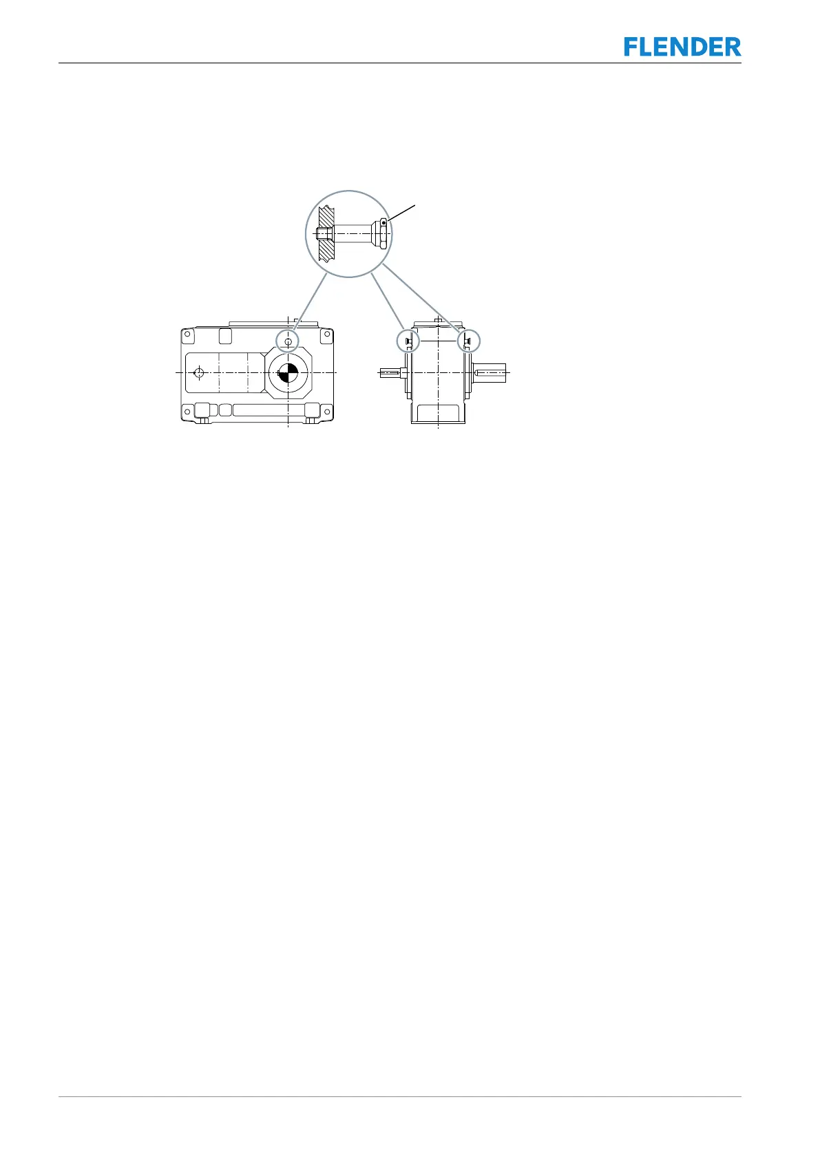
The diagram below shows a bearing monitoring system with shock-pulse transducer on type
K..H and K..M gear units:
Figure3-13:Bearing monitoring system with shock-pulse transducer on type K..H and K..M gear units:
Further information
You can find additional information and a detailed illustrated description of the gear unit and
the position of the mounted components in the dimension drawing, which is part of the com-
plete documentation of the gear unit.
3.13.2 Bearing monitoring by acceleration sensor3.13 Bearing monitoring
Depending on the order specification, the gear unit can be supplied with threaded holes in
which acceleration sensors can be inserted. These threaded holes have an M6 or M8 thread
depending on the variant.