Assembly
5.3 Gear unit assembly
A5850-02en Edition 06/2022 67
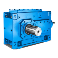
The following diagram shows the dismantling procedure using an end plate for gear units
with a hollow shaft and shrink disk:
Figure5-10:Dismantling using an end plate
① Pressure oil connector ④ Hollow shaft
② DU bushing ⑤ End plate
③ Machine shaft ⑥ Jacking screws
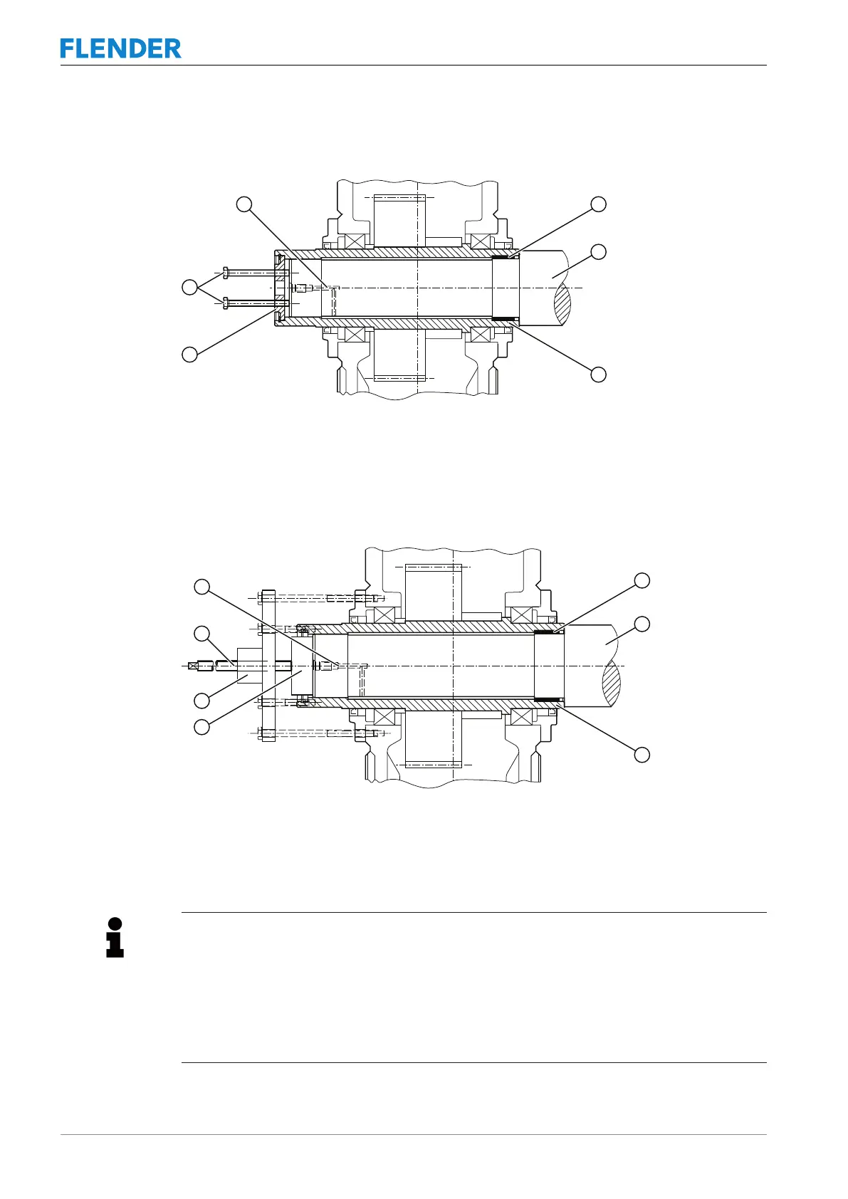
The following diagram shows the dismantling procedure using hydraulic pulling equipment
for gear units with hollow shaft and shrink disk:
Figure5-11:Dismantling using hydraulic pulling equipment
① Pressure oil connector ⑤ Auxiliary plate for pressing out
② DU bushing ⑥ Hydraulic pulling equipment
③ Machine shaft ⑦ Screw spindle
④ Hollow shaft
Information
The end plate and auxiliary plate are not included in the scope of delivery of the gear
unit.
The end plate and auxiliary plate for removing the gear unit are not supplied as standard
with the gear unit.
Both end faces of the hollow shaft have threaded holes for attaching the end plate to the
shaft.