Assembly
5.3 Gear unit assembly
62 Edition 06/2022 A5850-02en
Further information
You can find additional information about the connection dimensions of the driven machine
shaft in the dimension drawing in the complete documentation for the gear unit.
5.3.6.1 Preparations5.3 Gear unit assembly
To facilitate removal, Flender recommends that you insert a pressurized oil connection into
the shaft end of the driven machine until it is flush with the bore of the hollow shaft. This con-
nector can also be used to feed in rust remover. Failure to follow this recommendation shall
not give rise to any liability of the plant constructor towards the plant operator.
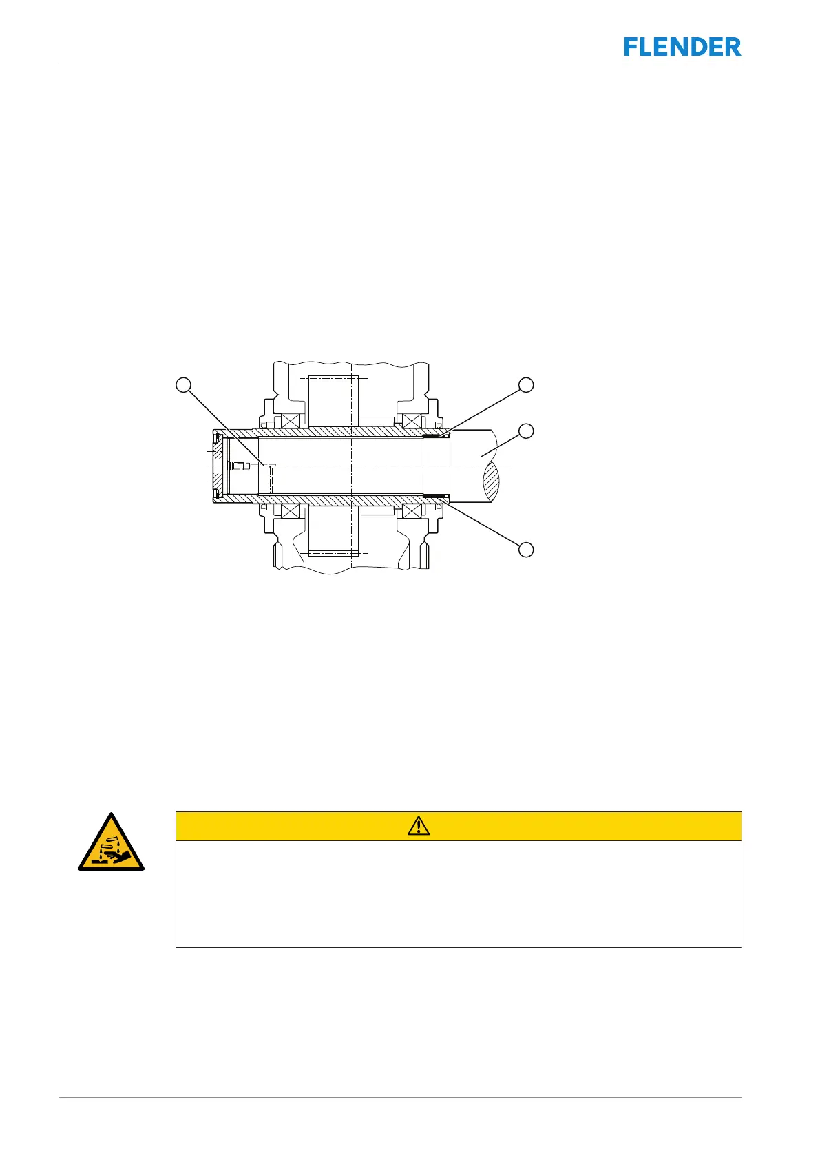
The following diagram shows the preparation for gear units with hollow shaft and shrink disk:
Figure5-8:Preparation for gear units with hollow shaft and shrink disk
① Pressure oil connector ③ Machine shaft
② DU bushing ④ Hollow shaft
See also
2 Dismantling (Page66)
5.3.6.2 Mounting5.3 Gear unit assembly
Measures to be taken prior to assembly
CAUTION
Risk of chemical burns due to chemical substances
There is a risk of chemical burns when handling corrosive cleaning agents.
Please observe the manufacturer's guidelines on how to handle cleaning agents and
solvents. Wear suitable protective equipment (gloves, safety goggles). Please use binding
agents to immediately clear up any spilt solvent.



 To Next Page