Assembly
5.3 Gear unit assembly
A5850-02en Edition 06/2022 61
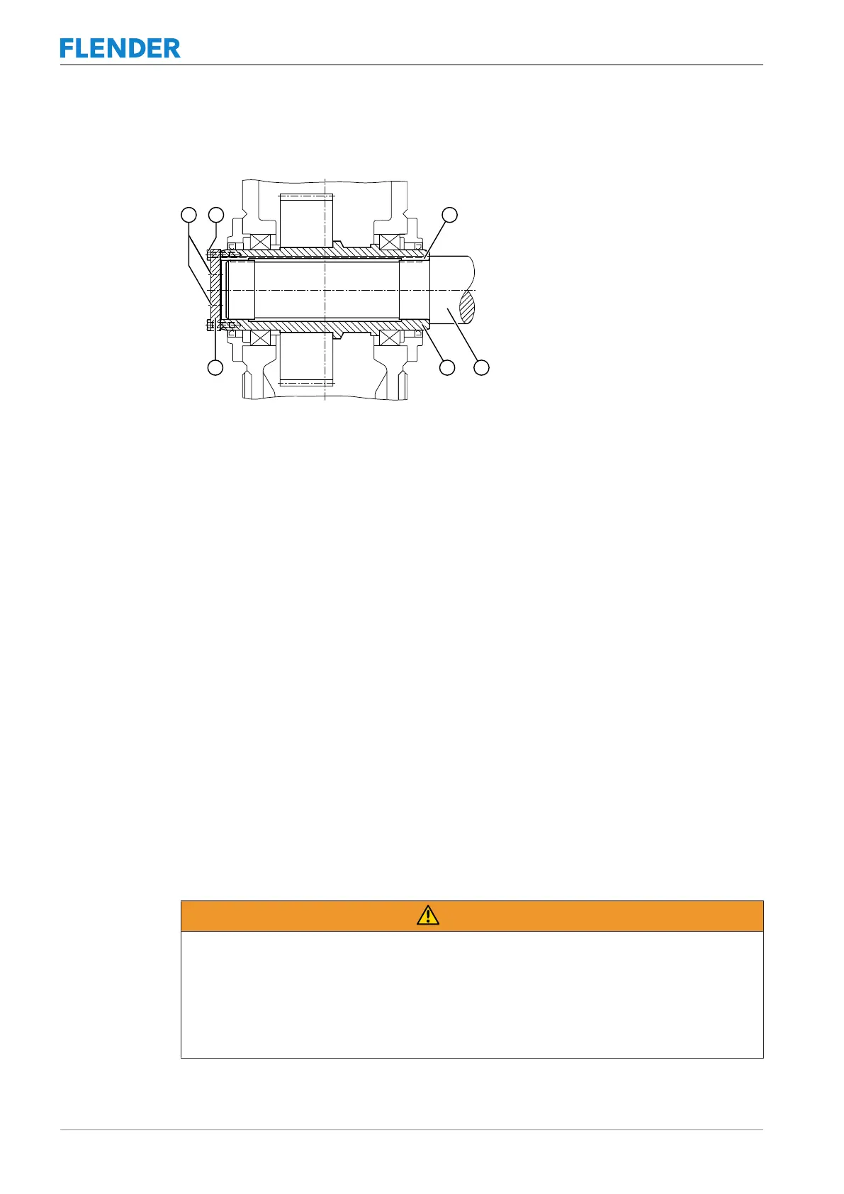
The following diagram shows the dismantling procedure using an end plate for gear units
with a hollow shaft and parallel keyway:
Figure5-7:Dismantling using an end plate
① Jacking screws ④ Machine shaft
② Bolts ⑤ Hollow shaft
③ Parallel key ⑥ End plate for pressing out
End plate and auxiliary plate
The end plate and auxiliary plate for removing the gear unit are not supplied as standard with
the gear unit. Both end faces of the hollow shaft have threaded holes for attaching the end
plate to the shaft.
Further information
You can find additional information and a detailed illustrated description of the threaded
holes in the dimension drawing, which is part of the complete documentation of the gear unit.
5.3.6 Shaft-mounted gear unit with hollow shaft and shrink disk5.3 Gear unit assembly
Introduction
The shaft end of the driven machine shaft (material C60+N or higher strength) should con-
tain a hole centred in its end face as defined by DIN 332, form DS (with thread). The connec-
tion dimensions for the driven machine shaft can be found in the dimension drawing in the
complete documentation.
WARNING
Risk of injury due to falling shrink disk or parts of the shrink disk
Injuries can be caused by the shrink disk falling or by flying fragments of the shrink disk.
Do not disassemble the shrink disk before you install it for the first time. Prevent the shrink
disk from slipping off the hollow shaft. If necessary, use suitable hoisting gear to lift and
transport the shrink disk. Arrange for qualified specialists to carry out the installation and
commissioning work.