Assembly
5.3 Gear unit assembly
A5850-02en Edition 06/2022 59
NOTICE
Damage to the rolling-contact bearings
The rolling-contact bearings can become damaged if the gear unit skews during mounting.
The hollow shaft may be mounted on a machine shaft shoulder only if the gear unit fea-
tures one of the following:
• Torque arm
• Elastic pedestal
• Supported by gear unit swing base
Proceed as follows to install the gear unit:
1. Use suitable hoisting gear to lift the gear unit.
2. Mount the gear unit using the nut and screw spindle.
The gear unit is braced by the hollow shaft.
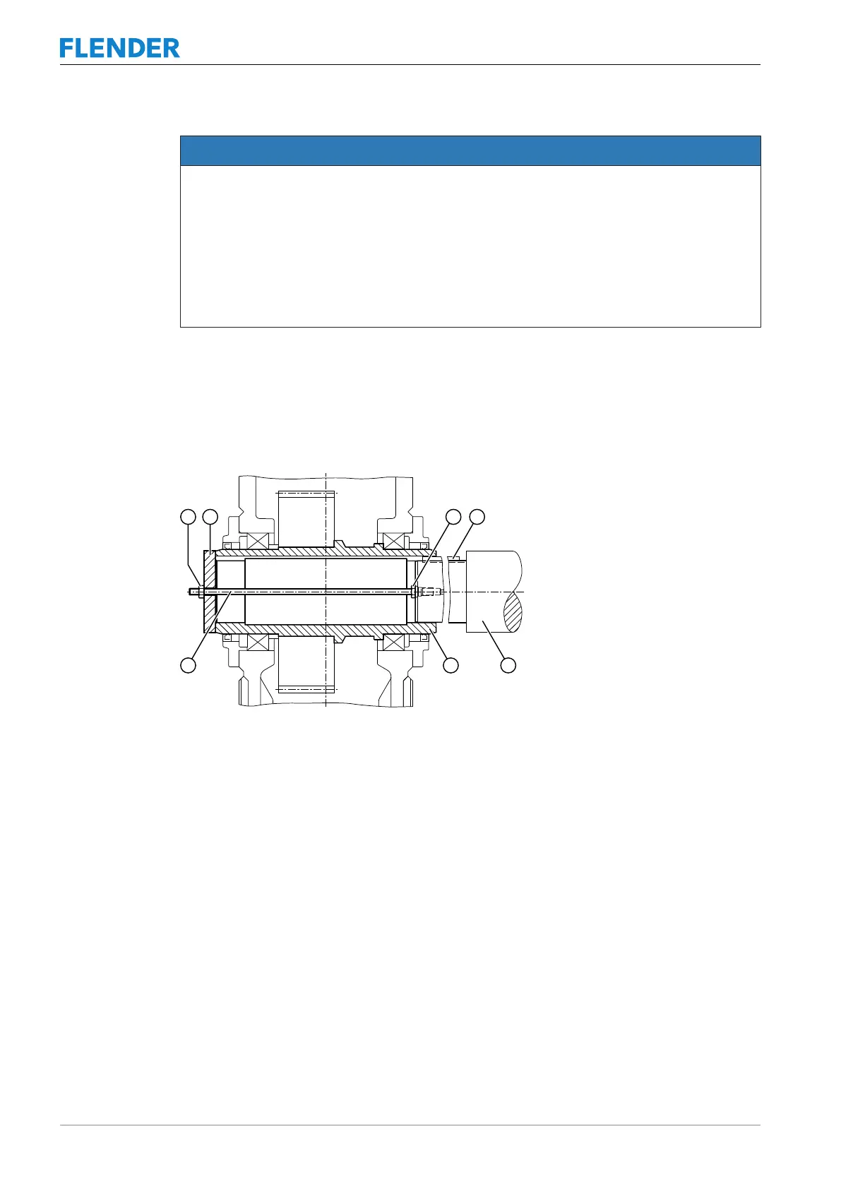
The diagram below shows the mounting process with screw spindle for gear units with a hol-
low shaft and parallel keyway:
Figure5-6:Mounting with a screw spindle
① Nut ⑤ Machine shaft
② End plate ⑥ Hollow shaft
③ Nut ⑦ Screw spindle
④ Parallel key
Hydraulic pulling equipment can be used instead of the nut and screw spindle shown in the
diagram.
5.3.5.2.2 Axial locking5.3 Gear unit assembly
Depending on the version, lock the hollow shaft axially on the machine shaft (e.g. by a
circlip, end plate, set screw).