Application planning
4.3 Attachment points
46 Edition 06/2022 A5850-02en
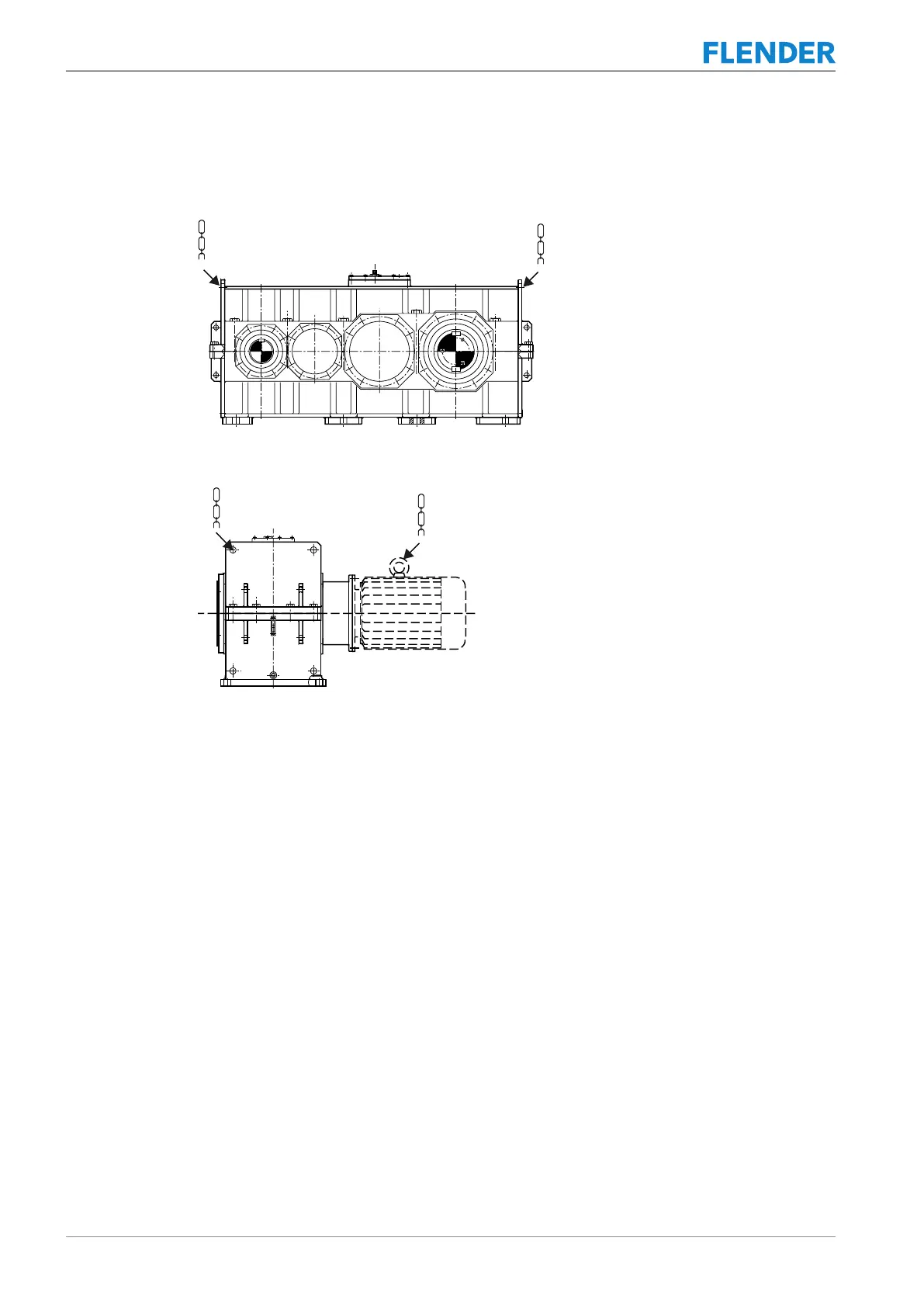
Position of attachment points
The following diagram shows the position of the attachment points on the gear unit:
Figure4-3:Position of attachment points on gear unit
The following diagram shows the position of the attachment points on a gear unit with motor:
Figure4-4:Position of attachment points on gear unit with motor
Drive units with additional components mounted on the gear unit (such as drive motor, coup-
ling, etc.) may require an extra attachment point owing to the displacement in the centre of
gravity caused by the mounted components.
Further information
You can find additional information and a detailed illustration of the gear unit, the position of
the attachment points, the centre of gravity and data on the weight in the dimension draw-
ings, which are part of the complete documentation of the gear unit.