Assembly
5.4 Couplings
72 Edition 06/2022 A5850-02en
Alignment
Align the individual components in two mutually perpendicular axial planes. The following
can be used as alignment tools:
• Ruler (radial displacement)
• Feeler gauge (angular displacement)
• Spirit level
• Dial gauge
• Laser alignment system
You will achieve a greater degree of alignment accuracy by using a dial gauge or laser align-
ment system.
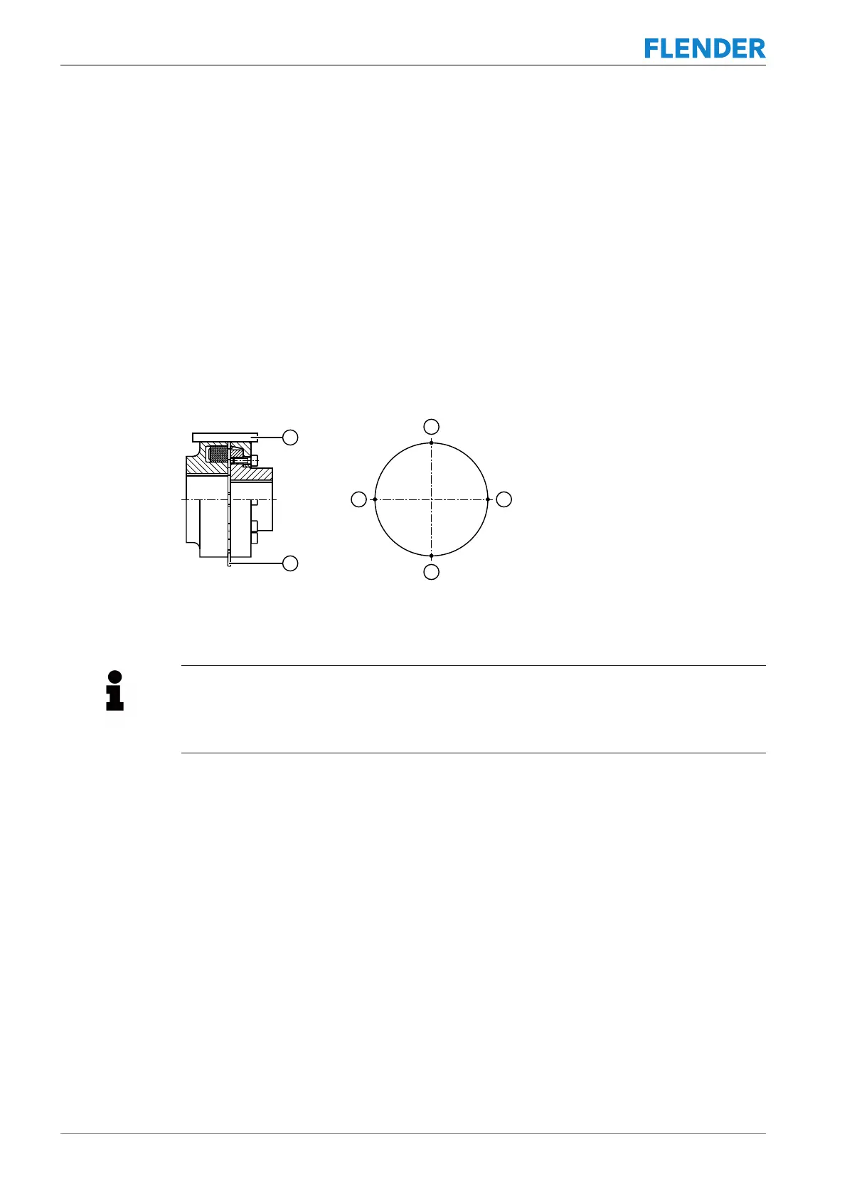
The diagram below shows the alignment process based on the example of a flexible coup-
ling:
Figure5-14:Alignment process based on the example of a flexible coupling
① Ruler ③ Measuring points
② Feeler gauge
Information
It is advisable to insert shims or metal sheets under the mounting feet in order to align the
drive components in the vertical direction. It is helpful to use support paws with adjusting
screws on the foundation to adjust the drive components laterally.
Gear unit with motor bell housing
If the gear unit and the motor are connected through a motor bell housing, no alignment of
the couplings is necessary.
Further information
Further information about the permissible alignment errors can be found in the coupling op-
erating instructions in the complete documentation for the gear unit, or contact the manufac-
turer in question.