Assembly
5.3 Gear unit assembly
A5850-02en Edition 06/2022 57
5.3.5 Shaft-mounted gear unit with hollow shaft and parallel keyway5.3 Gear unit assembly
Introduction
The shaft end of the driven machine shaft (material C60+N or higher strength) must have a
parallel key as defined by DIN 6885, Part 1, form A. Furthermore, it should have a hole
centred in its end face as defined by DIN 332, form DS (with thread). The connection dimen-
sions for the driven machine shaft can be found in the dimension drawing in the complete
documentation.
5.3.5.1 Preparations5.3 Gear unit assembly
To facilitate removal, Flender recommends that you insert a pressurized oil connection into
the shaft end of the driven machine until it is flush with the bore of the hollow shaft. This con-
nector can also be used to feed in rust remover. Failure to follow this recommendation shall
not give rise to any liability of the plant constructor towards the plant operator.
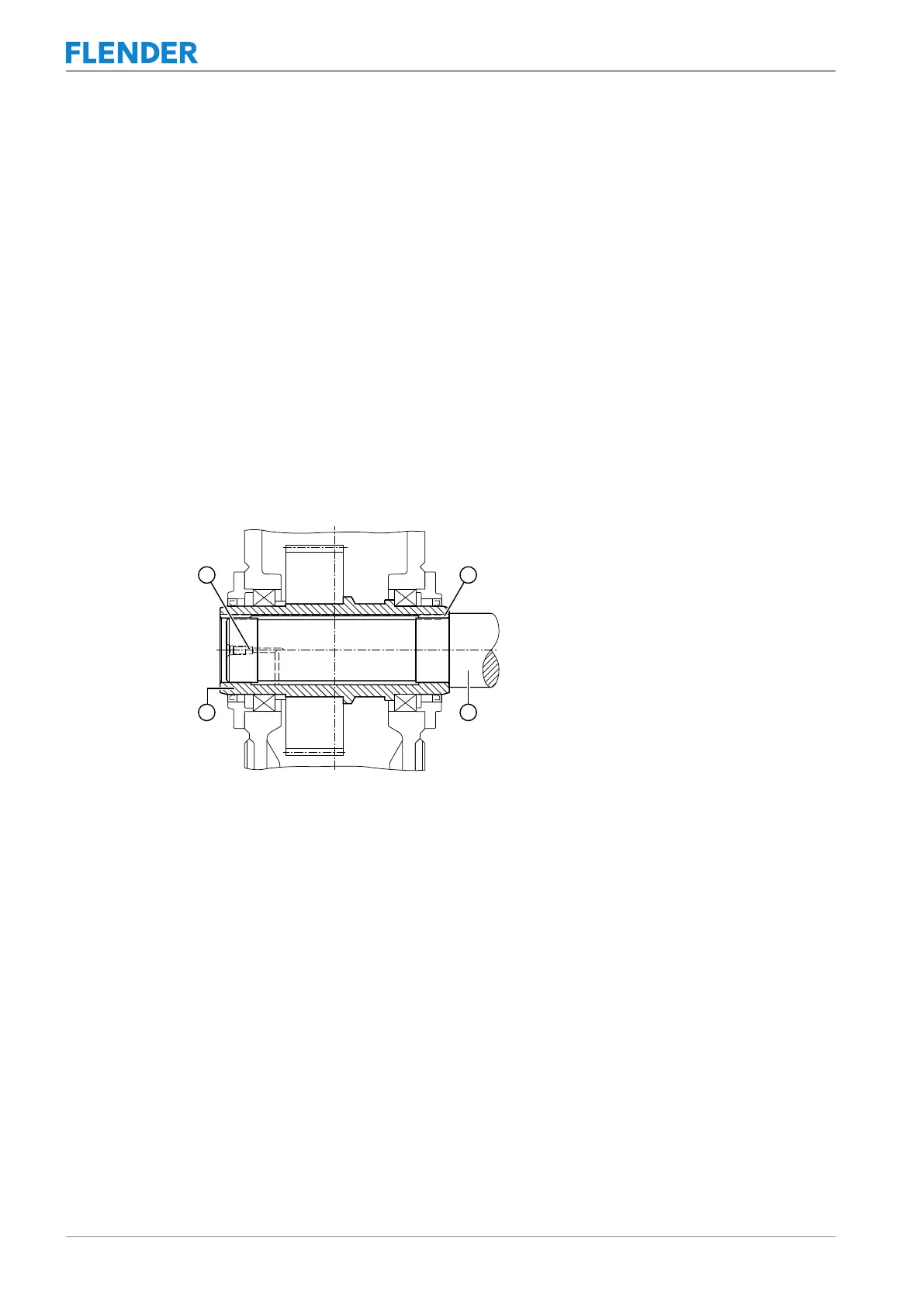
The following diagram illustrates the preparations required for gear units with a hollow shaft
and parallel keyway:
Figure5-5:Gear unit with a hollow shaft and parallel keyway
① Pressure oil connector ③ Machine shaft
② Parallel key ④ Hollow shaft
See also
2 Dismantling (Page60)