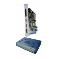
User Manual NTU Orion 2
25
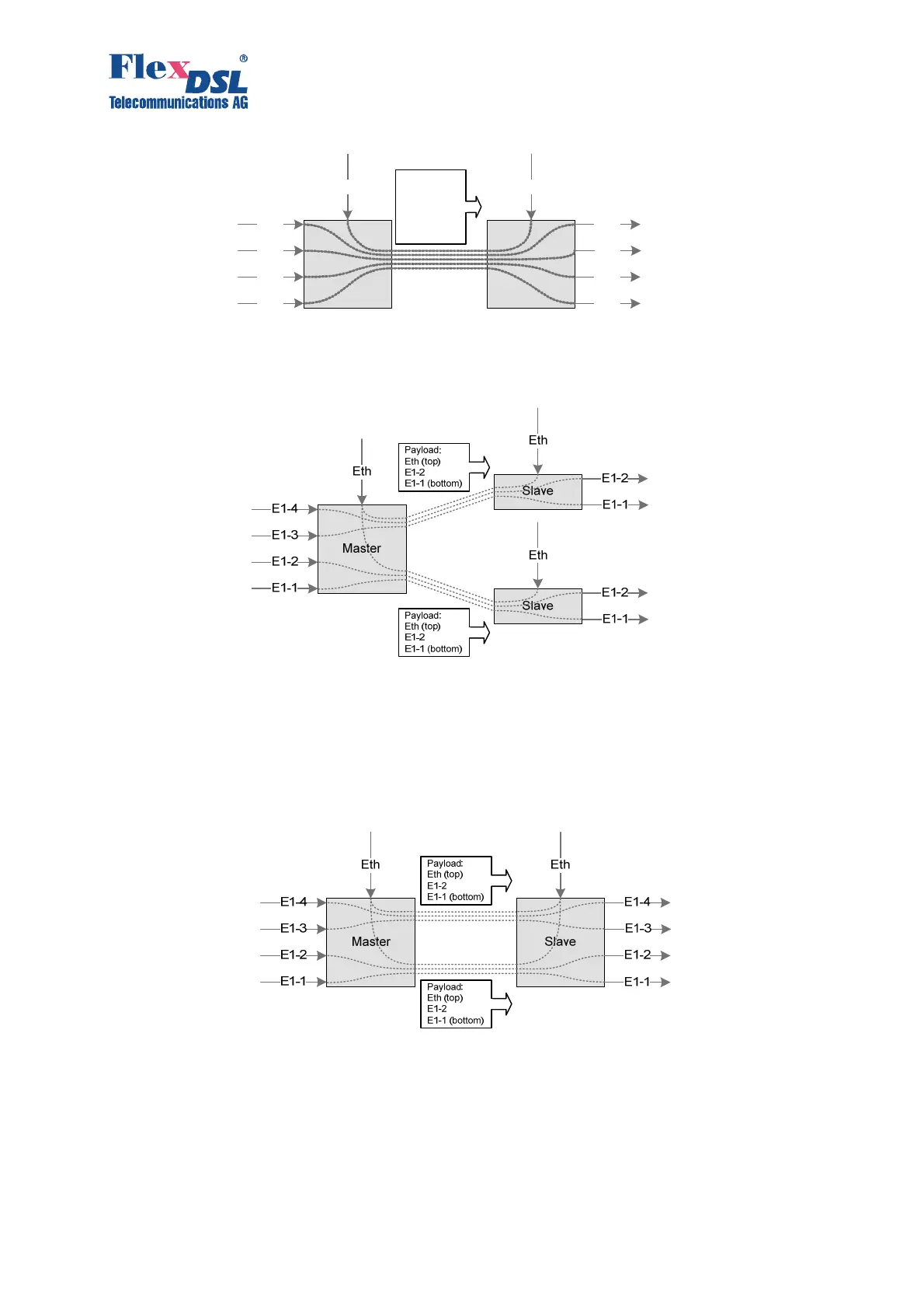
Four fractional E1 streams and Ethernet data are transmitted over one DSL link.
Figure. 3.8 Example No. 1 of automatic configuration of a link
The next example shows the start topology. The Master device is the center of the star, while
the rays, represented by the Slave devices, are configured automatically.
Figure 3.9 Example No. 2 of automatic configuration of a link
A more complex case is the independent two-channel connection: two E1 streams and Ethernet
packets are transmitted in the first channel and the second channel. The Slave device
determines the order of E1 interfaces for the streams from each DSL link only when
communication in both links is established.
Figure. 3.10 Example No. 3 of automatic configuration of a link
FlexDSL Orion2 regenerators are configured similarly to the above examples.
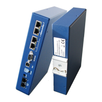
3.3.2.2 E1 interface (2 Mbit/s G.703/G.704)
The operation modes are described below refer to the E1 interfaces.
Master
E1-4
E1-3
E1-2
E1-1
Eth
Slave
E1-3
E1-2
E1-1
Eth
E1-4
Payload :
Eth (top)
E1-4
E1-3
E1-2
E1-1 (bottom )