User Manual NTU Orion 2
36
The G826 and G826 E1 command (the Performance management menu) are used to view the
G.826 error performance statistics.
3.3.5 BERT test
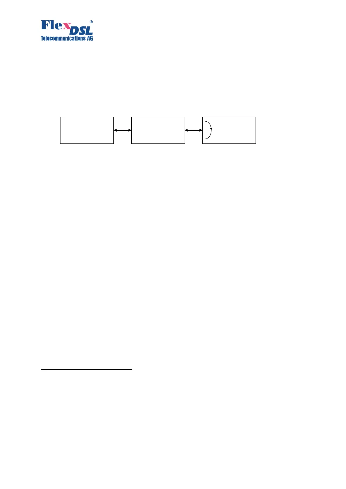
BERT testing is provided in a simple way. It’s preferred to switch on the Loop2 on the remote
unit (slave) and setup the BERT on the master unit.
Figure 3.18. BERT setup Example
Configuration Example:
CO_BERT>CONF
--------------------------------------------------------------------------------
Current BERT configuration:
--------------------------------------------------------------------------------
Interface : E1-1, Internal (to xDSL1)
Pattern : 2E7
TX Slots : [00-15] PG PG PG PG PG PG PG PG PG PG PG PG PG PG PG PG
: [16-31] PG PG PG PG PG PG PG PG PG PG PG PG PG PG PG PG
RX Slots : [00-15] BT BT BT BT BT BT BT BT BT BT BT BT BT BT BT BT
: [16-31] BT BT BT BT BT BT BT BT BT BT BT BT BT BT BT BT
--------------------------------------------------------------------------------
CO_BERT>
3.4 Alarm indication
When managing the device via the RS232 interface or via Telnet, all LEDs, except for Ethernet
LEDs will blink with a frequency of 1 Hz.
3.4.1 LEDs
The LEDs are used to display normal operation conditions and alarm conditions of a device
For NTUs in the plastic housing:
DSL 1 – a LED showing the status of the first line interface;
DSL 2 – a LED showing the status of the second line interface;
Eth – a LED showing the status of the Ethernet interface;
G.703 1 – a LED showing the status of the first Е1 interface;
G.703 2 – a LED showing the status of the second E1 interface;
DSL* – LEDs showing the status of line interfaces at connectors;
Eth* – LEDs showing the status of the Ethernet interface at the connector;
E1* – a LED showing the status of E1 interfaces at connectors.
Maste
Regenerato
Slave
E 1
Interface
1LOOP 2 1:R
BERT activated
Loop2 activated