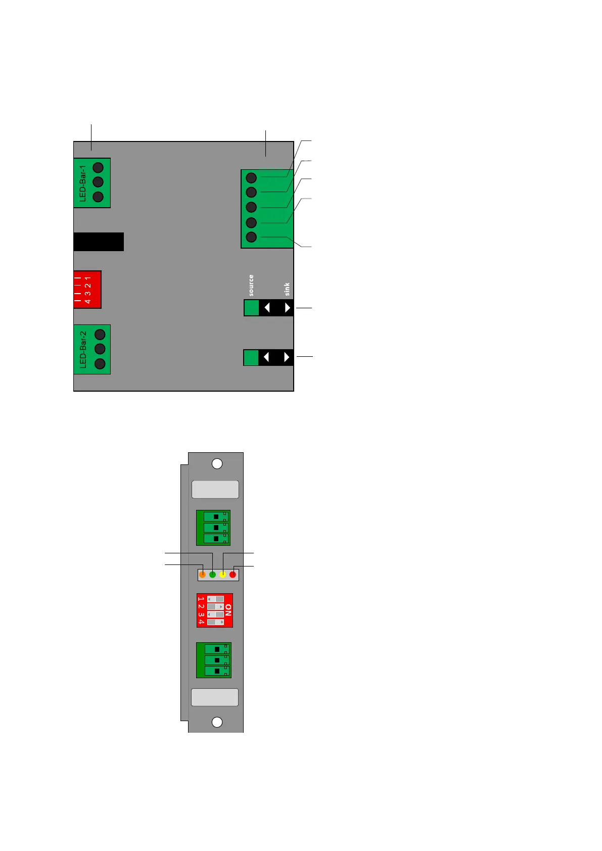
LEDs
FLASH ON
source/sink
STATIC ON
source/sink
OUT -
OUT +
OUT -
OUT +
READY
READY
DIP-switches
1 - 4
FLASH ON (input)
STATIC ON (input)
READY (output)
0 V
+24 V (input)
24V supply voltage, max. 1 A
output signal: 24V indicates, that the
backlight is ok
input signal: allows switching between flash and static mode.
IMPORTANT: if DIP switch 2 ON, then both backlight outputs
are ON (aktiv), independent of STATIC ON and FLASH ON.
input signal: connect the external trigger signal here to trigger the flash:
DIP Switch 1 = ON: flash on negative slope of FLASH ON
DIP Switch 1 = OFF: flash on positive slope of FLASH ON
0V supply voltage
FLASH ON switch:
setting ‘sink’: a 24V-signal on input of FLASH ON
sets it to logical 1.
Setting ‘source’: a 0V-signal (input on 0) on input of
FLASH ON sets it to logical 1.
STATIC ON switch:
setting ‘sink’: a 24V-signal on input of STATIC ON
sets it to logical 1.
Setting ‘source’: a 0V-signal (input on 0) on input of
STATIC ON sets it to logical 1.
3-pin Phoenix
connector
5-pin Phoenix
connector

 Loading...