flexfactory ag Quick Setup Guide and User’s anyfeed SX Series 33
4.3.2 ANYFEED SX RESPONSES
After receiving a command, the anyfeed SX will respond with specific characters to indicate
the status of each motor in the mechanism. Motor 1: The “flip” drive, located to the front of
the feeder, ander the feed surface. Motor 2: The “dispense” drive, located to the rear of the
feeder, ander the bulk container.
Response format: mix, where m = motor ; i = drive number (1 or 2) ; x = status of the drive.
Motor 2 anderstood command and is busy
Motor 1 anderstood command and is busy
Motor 2 completed action successfully and is OK
Motor 1 completed action successfully and is OK
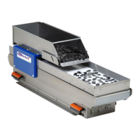
Sets the vision
trigger interval in
multiples of 20 ms
> ab[25]=[value]_x=25<cr>
Range for value is
1…63.
Default is 240 ms
(value=12)
Sets the vision
trigger delay in
multiples of 20
ms. The trigger
delay starts after
a feeder action
has completed.
> ab[26]=[value]_x=26<cr>
Range for value is
1…63
Default is 500 ms
(value=25)
Set the state of
the AnyFeeder's
internal digital
outputs. It is not
recommended to
set these during
normal operation,
only for
debugging
purposes.
Mode: 0: Engage
the dispense
clutch
1: Engage the flip
clutch
2:Turn backlight
OFF
3:Turn backlight
ON
4: Move retainer
gate UP
5: Move retainer
gate DOWN
Table 4-3 Serial Commands
 Loading...