Front Panel Operation
Connecting the Calibrator to a UUT 4
4-19
B.
UUT
HI
LO
A
HI
LO
GUARD
INPUT
SENSE
4-WIRE
HI
HI
LO
LO
HI
OUTPUT
V A
SENSE
V
AUX
CURRENT
GUARD GROUND
WIDEBAND
A.
UUT
HI
LO
A
HI
LO
GUARD
INPUT
SENSE
4-WIRE
HI
HI
LO
LO
OUTPUT
V A
SENSE
V
I-GUARD
V-GUARD
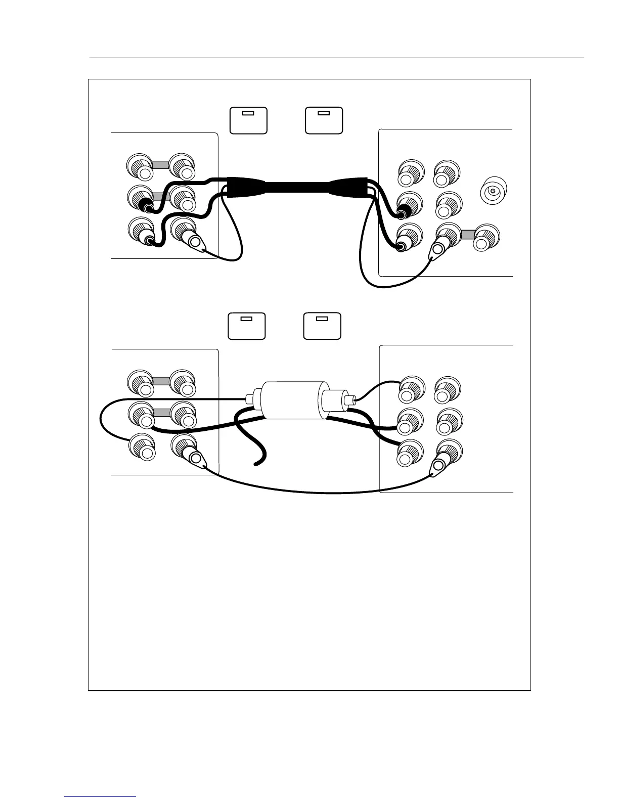
NOTE
The AUX CURRENT OUTPUT binding post is shown in use in figure 4-3A.
You can use the OUTPUT HI binding post or the 5725A Boost Amplifier
binding posts as the active terminals for current output. The operating
instructions in the text describe how you select the active terminal.
TRIAXIAL CABLE
EX SNS
: OFF
EX GRD
: OFF
If you do not select current output location, OUTPUT HI is active.
EX SNS
: OFF
EX GRD
: OFF
NC
Ω
Ω
Ω
Ω
Ω
Ω
CALIBRATOR
(FRONT)
CALIBRATOR
(REAR)
Figure 4-3. UUT Connections: AC Current ≤2A
 Loading...


