5700A/5720A Series II
Operators Manual
7-10
6. Enter the true value of the 732B 10V output. The true value is the value printed on
the calibration sticker, plus or minus, as well as drift that has occurred since
calibration. That drift can be estimated provided control charts have been maintained
for the 732B.
If the entered value is not between 9V and 11V, and error message appears, which
lets you start over from this point with a calibrated 732B. Press E, and the
display shows the following:
PREV
MENU
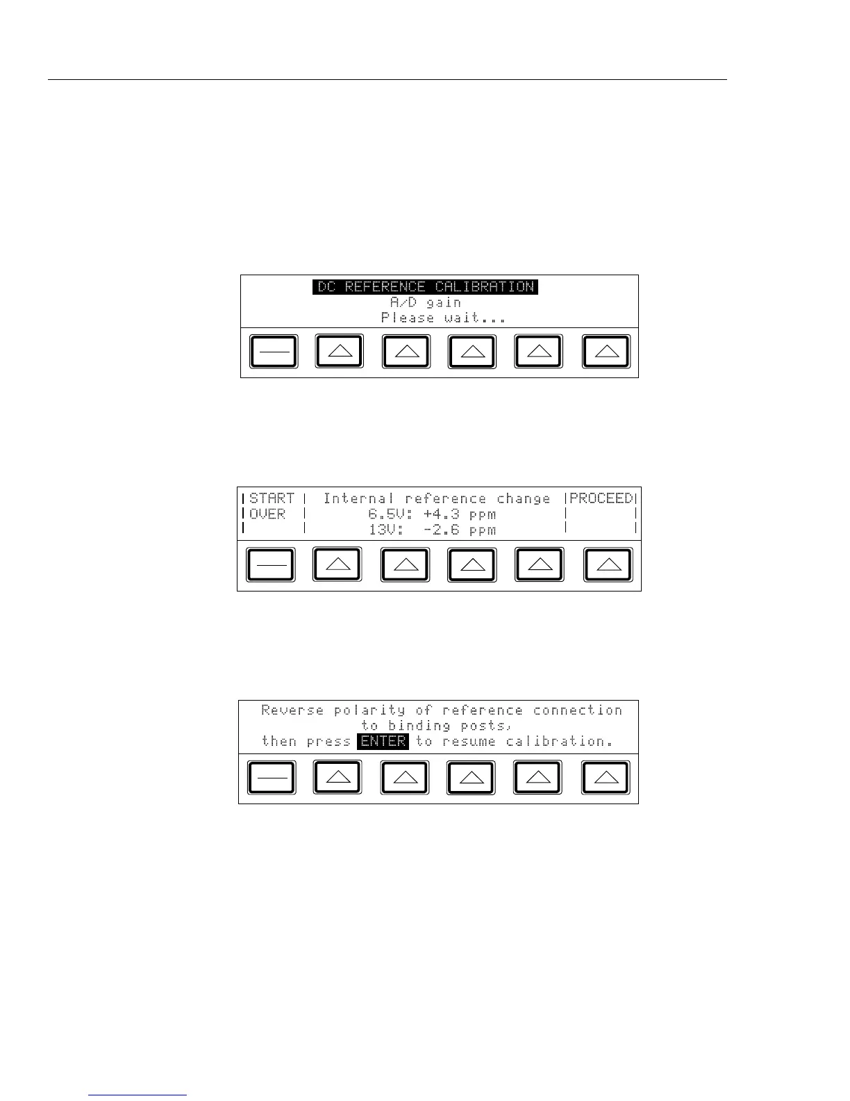
When the calibrator’s 6.5V and 13V references have been characterized, the display
shows the following message, which lets you accept or reject the changes that are
about to be made to the calibration constants.
PREV
MENU
7. To reject the changes, return to the calibration menu shown in step 2 by pressing
P. Otherwise, press the softkey under “Proceed” to accept and save the changes,
and to open the display shown below, letting you continue with calibration.
PREV
MENU