Chapter 9: Certify Fiber Cabling
Autotest in Loopback Mode
279
GPU119.EPS
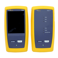
Figure 118. Result for Loopback Mode
Connector icons show the number you entered for the TOTAL
CONNECTIONS setting on the No. of Connectors/Splices screen
(Figure 108 on page 257). For Figure 118, the TOTAL
CONNECTIONS setting is 3.
The round icon shows the number of splices entered for the
SPLICES setting on the No. of Connectors/Splices screen.
To see help for the screen, tap .
When more than one button shows at the bottom of the screen,
the tester highlights one in yellow to recommend which one to
tap. See “Buttons to Do Tests and Save Results” on page 61.
D
G
E
F
A
B
C
H

 Loading...