63
10-2-5. Inverting GPI Output Pulse Polarity
To invert the polarity of GPI output pulse, change Polarity from Normal to Invert.
This function is used in such cases such as when inverting a tally condition, or using output
devices that work in inverse logic.
When connecting to FA-AUX30 units, set Polarity to Normal.
10-2-6. Sending GPI Settings
After all GPI settings are finished, click Apply to send all settings to the FA-10DCCRU unit.
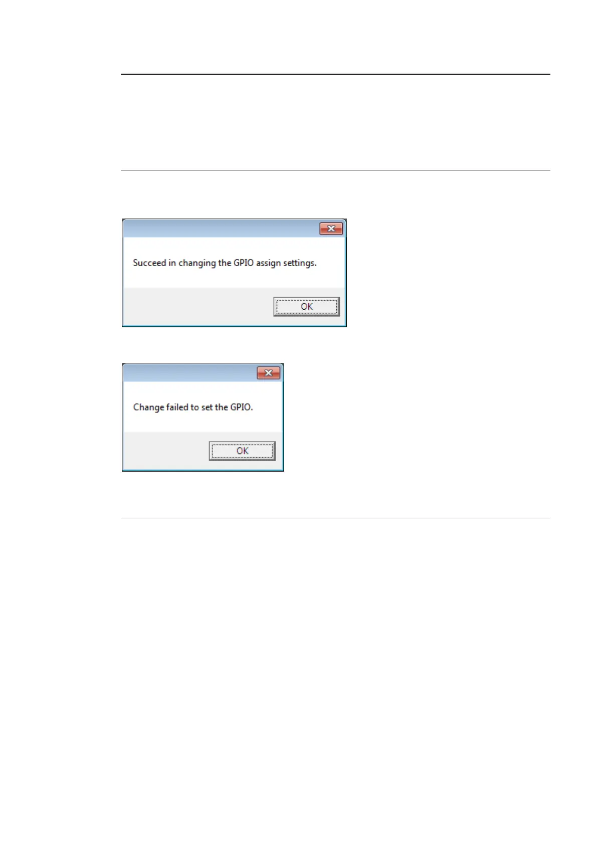
The following message indicates that GPI ports have successfully been set. Click OK to
close the dialog window.
The following message indicates that GPI settings have failed. Click OK to close the dialog
window. Verify the network connection and settings, then click Apply to reenter settings.
10-2-7. Pattern Load
The Pattern Load function allows you to assign GPIO functions in groups by loading patterns.
<Pattern Load Procedure>
(1) Click to select a tab from GPI Port 1 - 10(FA-AUX30 Left Block), GPI Port 11 -
20(FA-AUX30 Center Block) and Port 21 - 30(FA-AUX30 Right Block).
(2) Click on the Pattern box to select a pattern from the dropdown menu.
(3) Click Load to load the pattern. Ten GPI input/output ports are quickly set. Loaded settings
can be changed in the same manner as that of assignments. (See section 10-2-3. “GPI
Input Settings” and section 10-2-4. “GPI Output Settings.”)
(4) After all GPI settings are finished, click Apply to send the settings to the FA-10DCCRU
unit. If a “Successful settings” message appears, GPI settings are complete.
See section 10-2-8. “GPI Pattern List” for details on GPI patterns.