12
3. Panel Descriptions
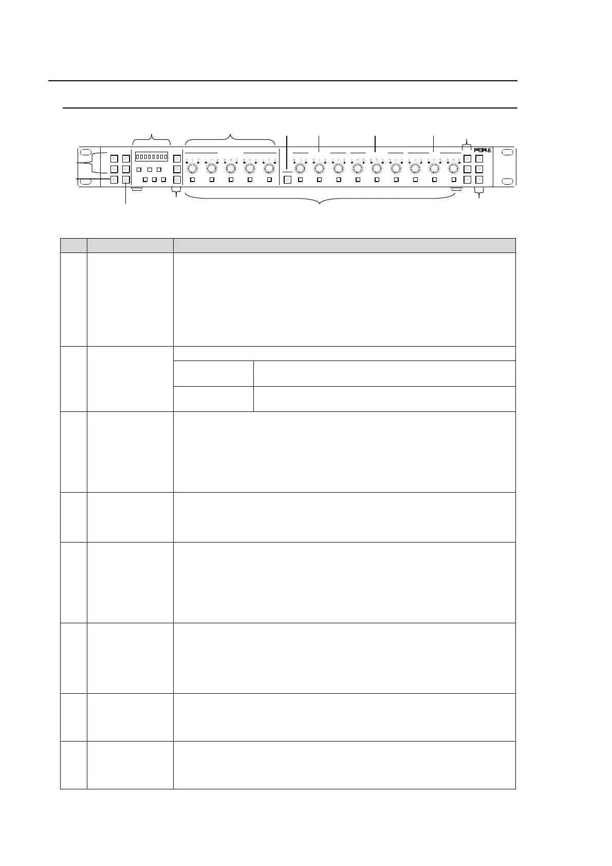
3-1. Front Panel
1-5,
6-10,
11-15/UNIT,
16-20
Main Unit selection buttons.
Before selecting Main Unit ID numbers with these buttons, assign Main
Units (FA-505, FA-1010, FA-9520 and FA-9500) to Unit ID numbers using
IP addresses.
See section 5-3-4. “Unit ID Assignment” and section 5-3-5. “Direct Mode
Settings” for more details.
Two connection modes are available: Direct and Unit. See section 6-1.
“Selecting Main Units.”
Allows you to select the operation mode by pressing the button.
Performs the correction and outputs the corrected
signal. (Operate mode)
Outputs the input signal without performing color
correction (Bypass mode)
Allows you to select an FS for which to adjust color correction settings
when connecting to an FA-505, FA-1010 or FA-9520 (in FA-9520 mode).
The button is disabled when connecting to an FA-9520 from FA-9500 or
FA-9500 unit. See section 6-3. “Selecting an FS Channel.”
Holding down the button allows you to select the Connection mode
between Direct and Unit. See section 6-1-3. “Selecting the Connection
Mode.”
Allows you to save settings to / load settings from memory as needed. See
section 7. “How to Use Event Memory.”
Setting values are displayed while saving or loading settings.
See section 9. “Information Display.”
Allows you to adjust Proc Amp settings in Color Correction mode (with
CLIP (10) unlit). See section 6-8. “Process Control” and section 6-9.
“Color Correction.”
Allows you to clip signal levels in Clip mode (with CLIP (10) lit) using the
three center buttons. See section 6-10. “Clipping Signal Levels.”
The settings apply to the selected FS if controlling an FA-505, FA-1010 or
FA-9520 in FA-9520 mode.
Allows you to adjust R, G, and B component levels (White, Black or
Gamma) all together.
While the button is lit, R, G and B component levels can be set together by
turning the R, G or B control button.
When holding down the button, the button blinks and the menu changes to
SYSTEM settings mode. See section 8. “System Settings.”
Allows you to adjust the white level. This setting is disabled in Sepia
mode.
The level adjustment applies to the selected FS if controlling an FA-505,
FA-1010 or FA-9520 in FA-9520 mode.
Allows you to adjust the black level. This setting is disabled in Sepia
mode.
The level adjustment applies to the selected FS if controlling an FA-505,
FA-1010 or FA-9520 in FA-9520 mode.
1-5 6-10
11-15/UNIT 16-20
BYPS/OP FS SEL
MEMORY/SET
0 1 2 3 4 5 6 7
FREEZE
CLIP
SPLIT
SELECT - +
SAVE LOAD CLEAR
VIDEO LEVEL Y LEVEL C LEVEL HUE
UNITY UNITY UNITY UNITY UNITY
SYSTEM
GRP ADJ
UNITY UNITY UNITY UNITY UNITY UNITY
R G B R G B
WHITE LEVEL BLACK LEVEL
UNITY UNITY UNITY
R G B
GAMMA
WHITE BAL
FA-10DCCRU
CENTER DIF
BLACK SEPIA
SETUP/BLACK
PROCESS CONTROL