34
6-10-1. YPbPr Clip
(1) With CLIP flashing, press DIF on the right end of the front panel to enable YPbPr Clip. (To
disable the function, press DIF again.)
(2) The following process control settings are available.
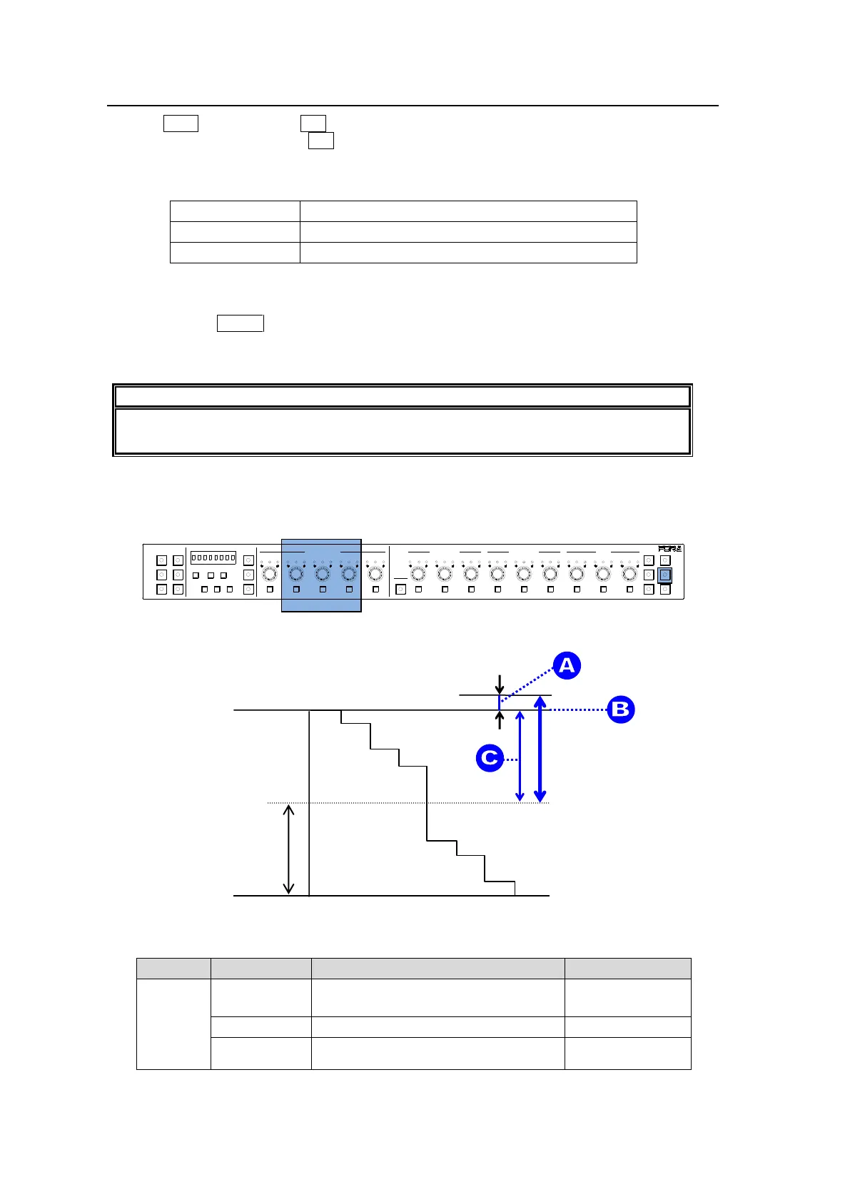
(3) Adjust the clip setting while viewing the three indicators above the controls and the value
on the MEMORY/SET display panel. (See “Signal levels and level display” below.)
Pressing the UNITY button below the value resets the clip value to the default.
(4) Repeat steps (2) and (3) to enter additional adjustments.
Note that changes are applied to all linked FS channels (FS Link On) in an FA-505,
FA-1010 or FA-9520 (FA-9520 mode). See section 11. “FS Link” for more details.
Signal levels and level display
The relationship between indicators, controls, and clip settings are as shown below.
① Y White Clip Level
Setting range: 50% - 109%
Default (UNITY): 109%
SMPTE 100% color bars when 100% white
Y White Clip
setting range
1-5 6-10
11-15/UNIT 16-20
BYPS/OP FS SEL
MEMORY/SET
0 1 2 3 4 5 6 7
FREEZE
CLIP
SPLIT
SELECT - +
SAVE LOAD CLEAR
PROCESS CONTROL
VIDEO LEVEL Y LEVEL C LEVEL SETUP/BLUCK HUE
UNITY UNITY UNITY UNITY UNITY
SYSTEM
GRP ADJ
UNITY UNITY UNITY UNITY UNITY UNITY
R G B R G B
WHITE LEVEL BLACK LEVEL
UNITY UNITY UNITY
R G B
GAMMA
WHITE BAL
FA-10DCCRU
CENTER DIF
BLACK SEPIA