15
1.5 Main Components and Functions
Inside
No. Name Description
1 Upper left cover Open this cover by lifting up the release lever to clear paper jams.
2 Bottom left cover Open this cover to clear paper jams.
When Tray 6 (HCF (A4 1 Tray)(optional)) is installed, open this
cover after moving Tray 6 to the left.
3 Adjusting foot Prevents the device from toppling over. Move the device to its
installation site and then rotate this adjuster in clockwise direction
until it touches a floor.
4 RESET button Automatically switches the device off when a current leakage is
detected.
5 Rear right cover Open this cover when connecting an interface cable.
6 Wireless Network Kit (Optional) You can connect wirelessly (Wi-Fi/Bluetooth) to this machine.
7 Ethernet Connector Connects to a network cable.
8 USB 3.0 interface connector Connect the USB cable to be connected to the computer.
9 USB 2.0 interface connector Connects a memory card reader, an optional component or a
peripheral with a USB cable.
10 Secondary Ethernet connector
(optional)
Connect a network cable here when the Secondary Ethernet Kit
(optional) is installed.
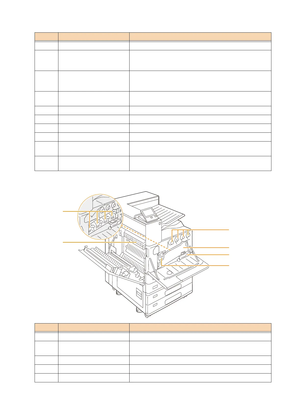
No. Name Description
1 Toner Cartridge Contains Black, Cyan, Magenta, and Yellow toner.
2 Conveyance box Remove this box when replacing a drum cartridge or cleaning the
interior of the device.
3 Waste Toner Container Collects waste toner.
4 Handle Unlock this handle when replacing a drum cartridge.
5 Fusing Unit Fuses toner on paper. Do not touch this unit as it is extremely hot.
 Loading...