Location and illustration
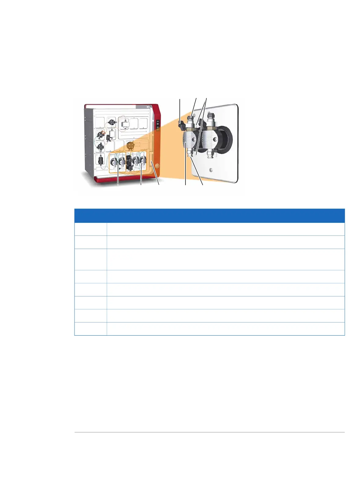
The illustration below shows the location of System pump A and System pump B, together with a detailed
view of a system pump.
DescriptionPart
Purge valve: Used to remove air from the pump1
Outlet port with check valve2
Connections to pump piston rinsing system: Tubing is connected between the pumps
and the Pump piston rinsing system tube (6)
3
Inlet port with check valve4
Pump head: Encapsulates the inner parts of the pump5
Pump piston rinsing system tube6
System pump B7
System pump A8
The pump piston rinsing system
A seal prevents leakage between the pump chamber and the drive mechanism. The seal is continuously
lubricated by the presence of liquid. The pump piston rinsing system continuously flushes the low
pressure chamber behind the piston with a low flow of 20% ethanol. This prevents any deposition of
salts from aqueous buffers on the pistons and prolongs the working life of the seals.
The pump piston rinsing system tubing is connected to the rearmost holes on the pump heads.
For instructions on how to fill the rinsing system, see Prime the system pump piston rinsing system, on
page 263.
ÄKTA pure User Manual 29119969 AB 35
2 The ÄKTA pure instrument
2.4 Instrument modules
2.4.1 System pumps