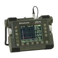
5-22 Issue 01, 04/2005 Krautkramer USM 35X
Operation Calibrating the USM 35X
Higher material velocity
Due to the V-path error, a higher material velocity than
that of the test material is given during calibration, es-
pecially with small thicknesses. This is typical of dual-
element (TR) probes and serves for compensation of
the V-path error.
With small wall thicknesses, the above-described effect
leads to an echo amplitude drop which has to be espe-
cially taken into account with thicknesses less than
2 mm/0.08".
A stepped reference block having different wall thick-
nesses is required for calibration. The wall thicknesses
must be selected so that they cover the expected read-
ings.
Calibration process:
We recommend to use the semiautomatic calibration
function for the calibration with T/R probes.
– Set the required test range.
– Increase the probe delay (P-DELAY) until the two
calibration lines are displayed within the range.
– Set the pulser and receiver functions according to
the probe used and the test application.
– Set the function TOF (function group MEAS) to
flank.
– Vary the gain so that the highest echo reaches
approximately the full screen height.
– Set the gate threshold to the required height for
measuring the sound paths at the echo flanks.
– Select the function group CAL.
– Enter the distances of the two calibration echoes in
S-REF1 and S-REF2.
– Position the gate (function aSTART) on the first
calibration echo.
– Press
to record the first calibration echo.
– Couple the probe to the calibration block containing
the second calibration line, and set the height so that
it’s about as high as the first calibration echo.
– Move the gate to the second calibration echo.

 Loading...


