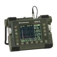
5-46 Issue 01, 04/2005 Krautkramer USM 35X
Operation
In principle, the peak measurement should be preferred
because the measured distances do not depend on the
echo height in that case. However, there are application
cases in which the flank measurement is either specified,
or it must be applied for technical reasons, e.g. in many
tests using dual-element (TR) probes.
A Attention:
In any case, the adjustment of the measuring point for
calibration and for the subsequent test use must al-
ways be identical. Otherwise measurement errors may
occur.
– Select the TOF function.
– Use the right-hand rotary knob to select the required
setting.
S-DISP (Zoomed display of reading)
You can have a selected reading zoomed in the A-scan
display. The following readings can be selected for the
zoomed display (in the second column the indication of
the readings in the measurement line):
Sa Sa Sound path for gate A
Sb Sb Sound path for gate B
Sb-a ba Difference of single measurements for
sound path gate B – gate A
Ha % Ha Echo height gate A in % screen height
Hb % Hb Echo height gate B in % screen height
Ha dB ha Echo height gate A in dB
Hb dB hb Echo height gate B in dB
R-start Rs Range start
R-end Re Range end
La La Number of legs in gate A
Lb Lb Number of legs in gate B
Lc Lc Number of legs in gate C
Only for flaw position calculation:
Da Da Depth for gate A
Configuring the USM 35X for a test application

 Loading...


