GE MEDICAL SYSTEMS
DIRECTION 2380207, REVISION 7 LOGIQ™5 PRO SERVICE MANUAL
5-20 Section 5-5 - Backend Processor
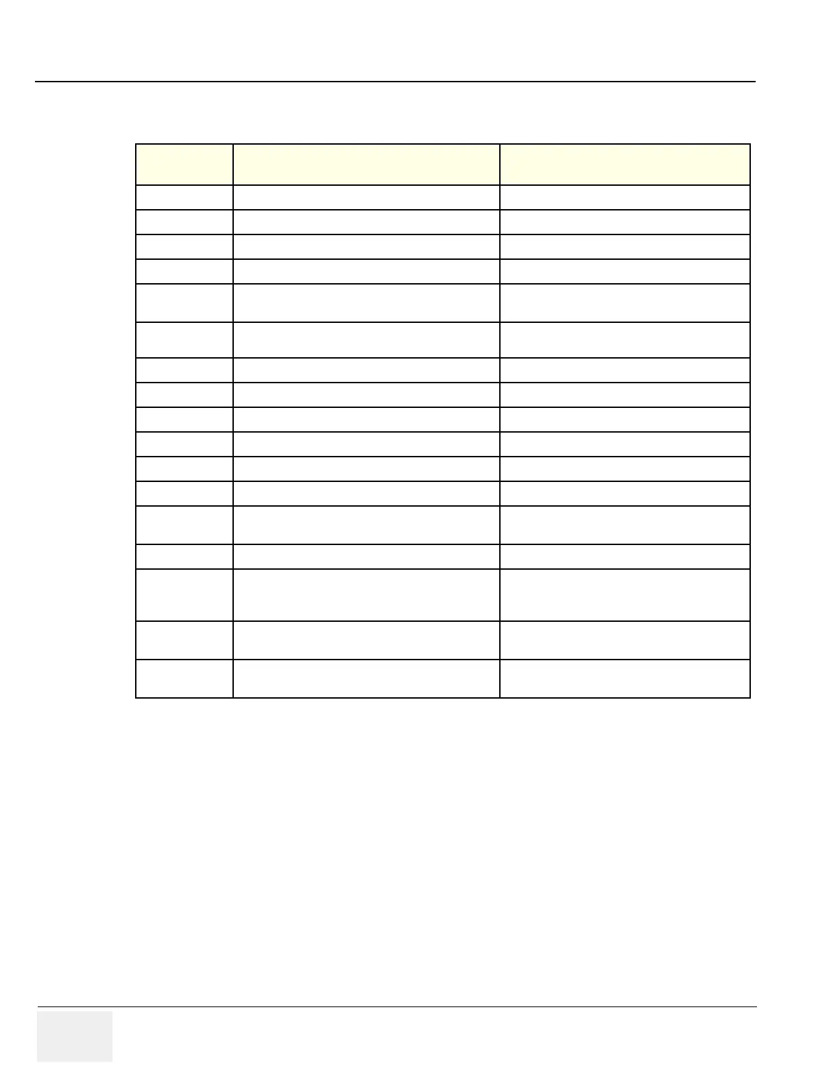
Table 5-4 Connector J2 (Peripheral Interface I/O)
Signal Name
(Pin No) Description Signal Path
Red Out (1)
Analog Red out signal for Color printer
VIC -> 44p DSub Conn Cable -> Rear Panel
Green Out(3)
Analog Green out signal for Color printer
VIC -> 44p DSub Conn Cable -> Rear Panel
Blue Out(5)
Analog Blue out signal for Color printer
VIC -> 44p DSub Conn Cable -> Rear Panel
CSYNC(7)
Composite Sync Signal for Analog Color Printer
VIC -> 44p DSub Conn Cable -> Rear Panel
BW Out 1(11)
Analog Video signal output to BW Printer for Front BW
printer
VIC -> Rear Panel -> OP Cable Assy -> BW Front
Panel
BW Out 2(41)
Analog Video Signal Output to BW Printer in Rear
Panel
VIC -> 44p DSub Conn Cable -> Rear Panel
SVHS Y Out((16)
Y Signal Output for S VHS recording
VIC -> 44p DSub Conn Cable -> Rear Panel
SVHS C Out((18)
C Signal Output for S VHS recording
VIC -> 44p DSub Conn Cable -> Rear Panel
Comp Out(20)
Composite Video Output for VCR recording
VIC -> 44p DSub Conn Cable -> Rear Panel
SVHS Y In(22)
Y Signal Input for S VHS Playback
VIC -> 44p DSub Conn Cable -> Rear Panel
SVHS C In(37)
C Signal Input for S VHS Playback
VIC -> 44p DSub Conn Cable -> Rear Panel
Comp In(24)
Video Composite Input for VCR Playback
VIC -> 44p DSub Conn Cable -> Rear Panel
BW Shutter 1
Shutter Signal Out for BW Printer on Front
VIC -> 44p DSub Conn Cable ->Rear Panel -> OP
Cable Assy -> BW Front Panel
BW Shutter 2
Shutter Signal Out for BW Printer on Rear
VIC -> 44p DSub Conn Cable ->Rear Panel
VGA R(31), G(33),
B(35), HS(39),
VS(26)
VGA Signal for External VGA Monitor Port in Rear
Panel
VIC -> 44p DSub Conn Cable ->Rear Panel
DC12V(13)
DC 12Volt Power for Isolation Circuit and Switch
Circuit for Speaker Sound in Rear Panel
BEP Motherboard -> VIC -> 44p DSub Conn Cable
-> Rear Panel
DC5V(15, 30)
DC 5Volt Power for EEPROM in Rear Panel
BEP Motherboard -> VIC -> 44p DSub Conn Cable
-> Rear Panel


 To Next Page